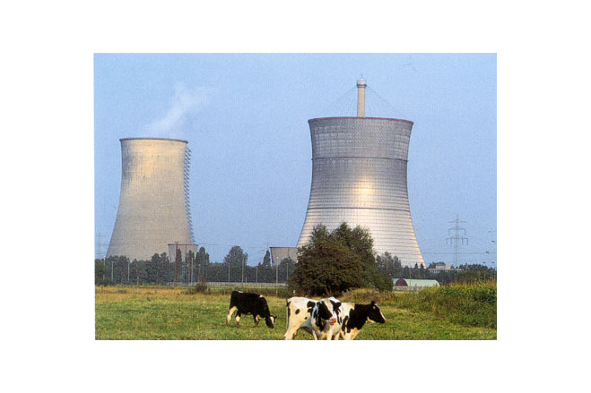
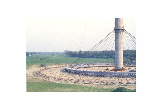
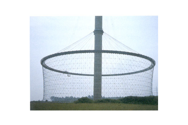
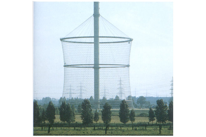
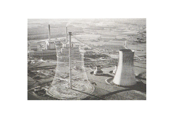
Cable-net Cooling Tower in Schmehausen
General information
-
Location address
Schmehausen
-
Location country
Germany
-
Year of construction
1971
-
Name of the client/building owner
Vereinigte Elektrizitätswerke (VEW) Dortmund
-
Function of building
Industrial buildings
-
Climatic zone
Temperate - cold winters and mild summers
Description
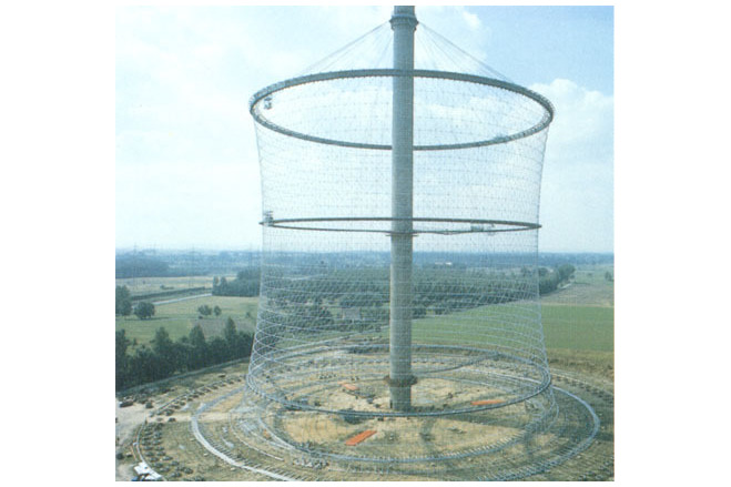
The innovatieve Cable-net cooling tower at Schmehausen evolved in response to two factors. The first was the increasing public demand for electricity, which was leading to a constant increase in the size of power stations. The second was a desire to change to a new and less environmentally damaging form of cooling.
In the decades leading up to the 1970s, cooling towers had taken the form of reinforced concrete hyperbolic paraboloids. With the radii becoming very large in comparison to the thickness, the stiffening effect of the dual curvature of the shell was becoming much lless effective. When its curvature was measured in terms of its thickness, the wall could be described as almost flat. The ability of the shell to resist localized wind pressures was thus placed in question. Cooling towers at Ferrybridge in England had recently collapsed due to the effect of wind gusts ( exacerbated by funnelling between adjacent towers) which caused resonant deformation of the horizontal cross-section. In addition, relatively minor inaccuracies in the shaping of the shells during constructions were becoming more significant and were leading to an increased danger of buckling. The shells were also very sensitive to differential settlement of their supports. It seemed that a limit on the size of concrete cooling towers was fast being reached.
Balcke-Dürr of Ratingen, a firm which specialized in the design of cooling towers, had been wrestling with this problem for some time. In 1972, a representatieve approached Schlaich at the Leonharddt an Andrä offices with suggestion that the solution might be to form cooling towers from cable nets covered with an apropriate cladding material.
It happened that, since his experience at Munich, Schlaich had been ponderinng the problem of the high deformability of rectangular meshes which have cables running in only two directions. This can be overcome by adding a third set of cables to produce a triangular mesh, but there is a price to pay: the resulting system is applicable only to a limited number of regular, mathematically defined surfaces.
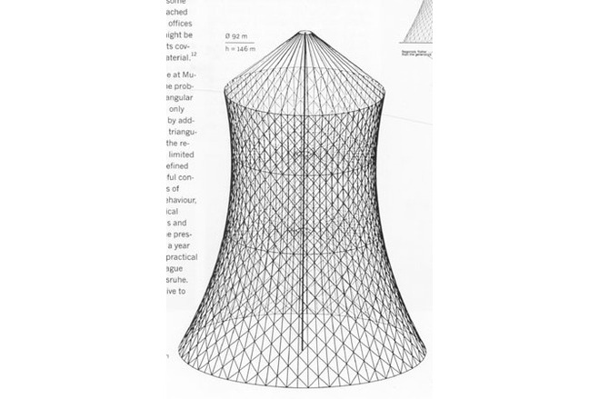
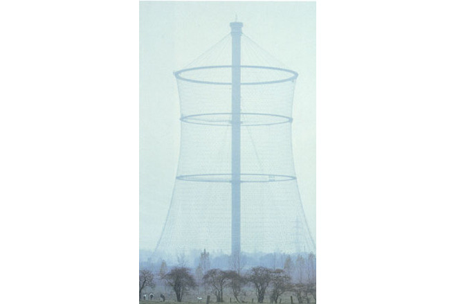
The Vereinigte Elektrizitätswerke (VEW) of Dortmund accepted Balcke-Dürr's proposal to use a cable-net tower for their 300MW thorium high-temperature reactor in Schmehausen in Hamm-Uentrop. The conformation and height of the tower were determined by the thermodynamic requirements and the arrangement of the heat exchangers and air intakes. These defined a mantle 146 metres high with a diameter of 141 metres at the base and 92 at the top. Schlaich's colleagues in the design were Günter Mayr, Jürgen Noesgen and Josef Eibl.
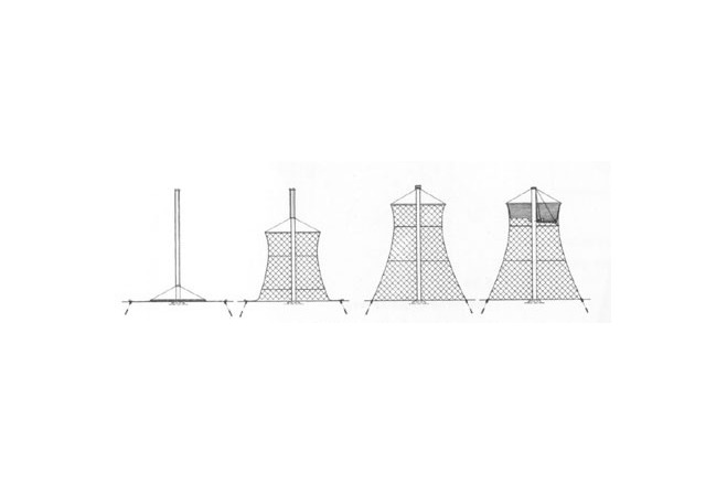
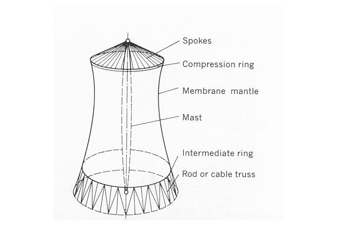
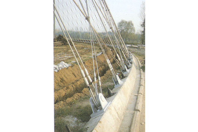
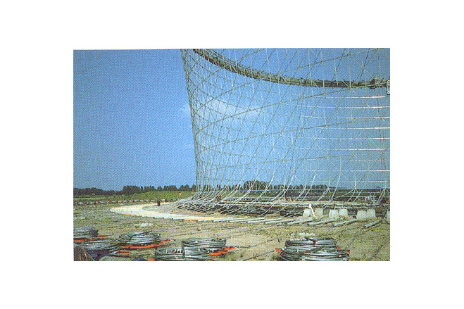
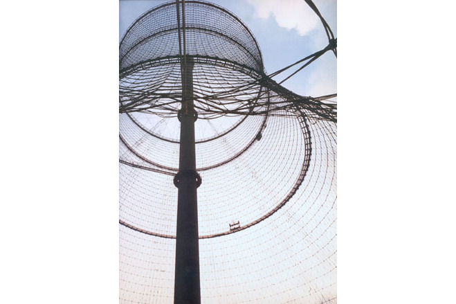
The basic concept was to support the upper rim from a central mast. In the early planning stages the team seriously considered forming the surface from a true shell made of aluminium or stainless steel sheeting. This would have been prestressed to control deformation due to self-weight and wind load. However, investigation showed that the difficulties and expense of fabrication and the cost of temporary stays to resist the wind pressures to be expected during erection would outweigh the advantages. It was therefore decided to use a cable net to carry the loads, and clad it with sheets of metal or plastic which need spa only the width of the mes. The thickness of the corrugated aluminium sheeting eventually used for this purpose was one millimetre.
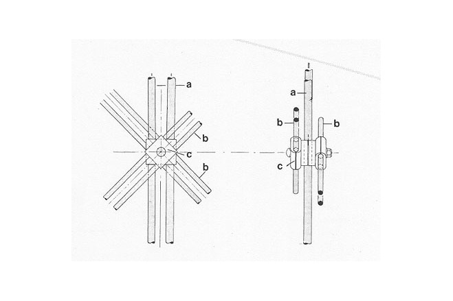
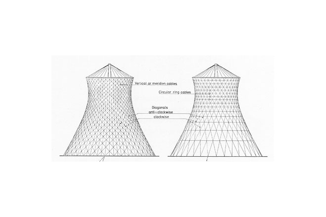
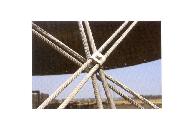
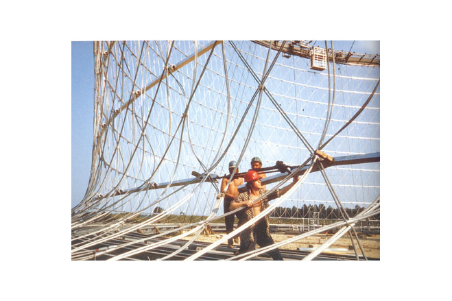
The next question was the arrangement of the cables. The hyperbolic paraboloid form of a cooling tower may be defined by a horizontal circle at top and bottom with two families of straight cables streched between them lying on the generators of the surface. However, to add a third layer of cables and to prestress all three layers simultanuously it is essential to give the two layers of cables an inclination greater or less than that of the generators, so that they follow a curved path in space. If the main cables run at aless steep (flatter) angle than the generators, they follow a trajectory which loops outwards around the surface of the tower. When pretension is applied, t
Description of the environmental conditions
Electric power stations produce vast amounts of waste heat. In some cases this is carried away by cooling water which is obtained from, and returned to, nearby lakes or rivers, seriouslyi interfering with their ecological balance. A somewhat less objectionable method is to discharge the heat to the atmosphere by means of a cooling tower - a form of huge chimney. Steam from the cooling system is blown in at the base and the resulting updraft drwaws in air through slots at the bottom of the tower. As the steam evaporates, it transmits its heat to the air and much of it falls back like rain. However, a great deal of water escapes from the top of the tower and this must be continuously replaced witth water from rivers and lakes. The process is detrimental to the climate and competes with domestic water supplies. (the water consumption of one typical cooling tower is equal to that of a city of 200000 inhabitants.) The requirement for adequate water supply also places restrictions on the location of power stations. For these reasons there was a move towards the use of the so-called dry cooling system in which both water and heat are largely retained in a closed cycle. The only problem is that this system requires much larger cooling towers: about twice the size of "wet" ones, and up to 300 metres in height.
[The Art of Structural Engineering, Alan Holgate, p90]
General comments, links
In 1991, for a combination of political and safety reasons, the nuclear power plant was closed down and scheduled for demolition. On 9th of July 1991 it was brought down by explosives.
The Art of Structural Engineering: The Work of Jörg Schlaich and his Team
Material of the cover
-
Cable-net/Fabric/Hybrid/Foil
Cable
Main dimensions and form
-
Total length (m)
141
-
Total width (m)
92
Duration of use
-
Temporary or permanent structure
Temporary
-
Convertible or mobile
Convertible
-
Design lifespan in years
00-05
Editor
-
Editor
Marijke M. Mollaert


