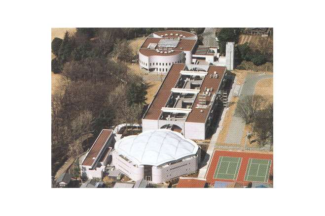
Kaetsu Memorial Gymnasium in Tokyo
General information
-
Location address
Tokyo
-
Location country
Japan
-
Year of construction
1985
-
Name of the client/building owner
Kaetsu Women's Junior College
-
Function of building
Sport
-
Degree of enclosure
Fully enclosed structure
-
Climatic zone
Temperate - cold winters and mild summers
Description
Design
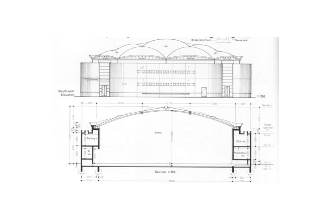
The site of this gymnasium for the women's junior college of the Kaetsu University in Tokyo is located in an area classified as residential according to the development plan (class A according to the Japanese building regulations) whereby the building height of residential buildings is limited to 12 m. One of the design requirements of the client, the Kaetsu University, was therefore, that all rules and regulations of the development plan should be fulfilled without waivers and at the same time a usable space with an interior height of 11.5 m as required for national volleyball tournaments had to be created.
In addition the university allowed no excavation into the ground. This left a mere 0.5 m for the roof structure including the roof build up. A further essential aspect in designing a gymnasium is good natural lighting. Also desired was a ?green? building, friendly to the environment, using natural lighting and natural ventilation. Only a membrane structure could fullfil all these demands.
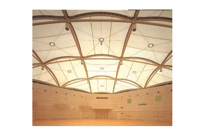
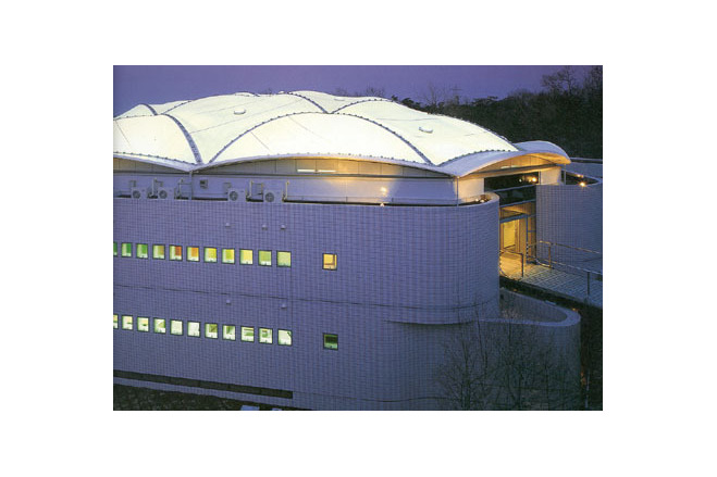
A wide-span, translucent roof illuminates the arena with diffuse, glare-free and still direct sunlight. To match this, the architects wanted to create a visually soft and harmonious space colorised in shades of white. A favourable precondition for this design was that the confidence of planners and client in the possibilities of a membrane roof had recently been strengthened by the successful completion of the Kajima Pneudoms as a translucent roof for a tennis court.
Plan
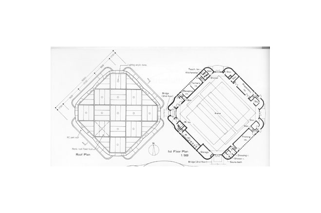
On a site of 23 300 m² a building emerged with a plan area of 1260 m² and a floor space of 1603 m². The plan shape is square. The entrance areas are situated in the re-entrant and well rounded corners of the plan square. Above them the plant rooms for ventilation and air conditioning are located. The ancillary rooms are arranged along the sides of the plan square in four narrow, two-storied wings with flat roofs. On the 1st floor there are the locker rooms with showers, toilets and the sauna, the storerooms, training and preparation rooms as well as the rooms for the P.E.instructors ; the 2nd floor contains recreational and club rooms.
Structure
The parasol dome is supported by a curved two-way grid structure, rectangular in plan, and made from steel tubes (Ø 139.8 x 6 mm). Frei Otto would probably call it a grid shell. The two-way grid in plan has square and triangular meshes and twin edge arches (Ø 89.1 mm) and is covered with individual panels of PTFE-coated glass fibre fabric. The building is supported on pile foundations. Due to typhoon exposure the design wind speed is as high as 60 m/sec (216 km/h).
Description of the environmental conditions
Roof membrane
The membrane panels are composed of PTFE-coated glass fibre fabric. They are prestressed by a cable system running diagonally from node to node of the structural grid and fixed to a central membrane ring, so that a sufficient membrane curvature is provided to carry the wind uplift.
Various new structural details and methods were developed, among others
- a detail to prestress the membrane from a fixed edge,
- an aluminium edge clamping section, replacing the traditional membrane clamps with bolts and clamping plates, thus avoiding perforating and weakening the membrane at this point, and
- the design of the central prestressing rings with cables and pulleys.
At the low point the membrane has a circular cut-out with an edge boltrope, which is held in a two-piece ring, made of a circular (annular) boltrope profile. At the lower ring rollers (Ø 36 mm) are connected, pulling down the low point using diagonal cables (spiral strand Ø 10 mm with a 2-mm polyamide sheathing) against the primary structure. The low point rings are closed with an acrylic dome light (Ø 600 mm) above and planar wire glass below.
Along the membrane edge runs a boltrope, anchored in a two-piece boltrope section (b 65 mm), bolted to two steel angles (L 90 x 7) above and below. The angles are pulled toward the outside by horizontal stainless steel tensioning bolts (below M20, above M12) and against the grid tube via a welded steel plate web with a stiffening steel-flat top chord, thus prestressing the membrane. A neoprene gasket with a zipper profile provides a seal against the neighbour panel. The seal at the building edge against the GRC shells is achieved in a similar way using a neoprene gasket fixed in a groove and a butyl seal.
Building construction
For the inside surfaces new types of finish were used which had never previously been used in this form in Japanese gymnasiums, also new materials, among them acoustic wall panels from basswood, finished with a light whitewash coat. Below the acoustic wall cladding there is a new type of basswood insulation material.
Assembly
The scheme design was started in July 1984 ; the detail design was completed in July 1985 ; the construction period totalled 8 months for the conventional structure and 2 months for the roof membrane.
[Soft Shells, Hans-Joachim Schock, p82-84]
Material of the cover
-
Cable-net/Fabric/Hybrid/Foil
Cable
-
Material Fabric/Foil
Fiberglass
-
Material coating
PTFE
Main dimensions and form
-
Covered surface (m2)
1260
-
Total length (m)
29.4
-
Total width (m)
29.4
Duration of use
-
Temporary or permanent structure
Temporary
-
Convertible or mobile
Convertible
-
Design lifespan in years
00-05
Involved companies
-
Architects
Kajima Design
-
Engineers
Kajima Design
-
Contractors
Taiyo Kogyo Corporation
Editor
-
Editor
Marijke M. Mollaert


