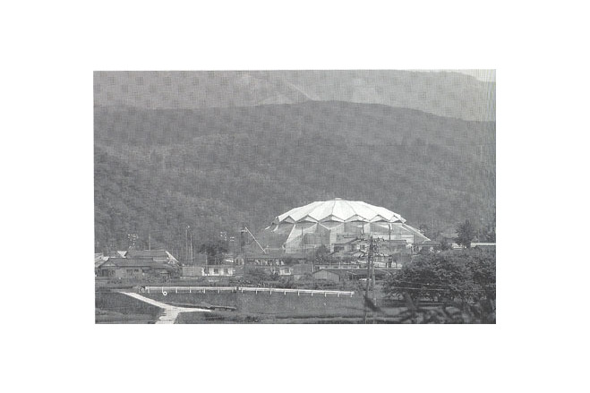
Amagi Dome


General information
-
Location address
Amagi yugashima-cho
-
Location country
Japan
-
Year of construction
1991
-
Name of the client/building owner
Amagi yugashim-town
-
Function of building
Sport
-
Degree of enclosure
Fully enclosed structure
-
Climatic zone
Temperate - cold winters and mild summers
-
Number of layers
mono-layer
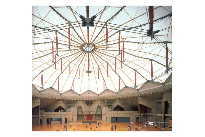
Description
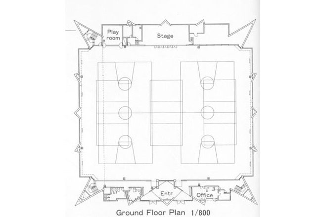
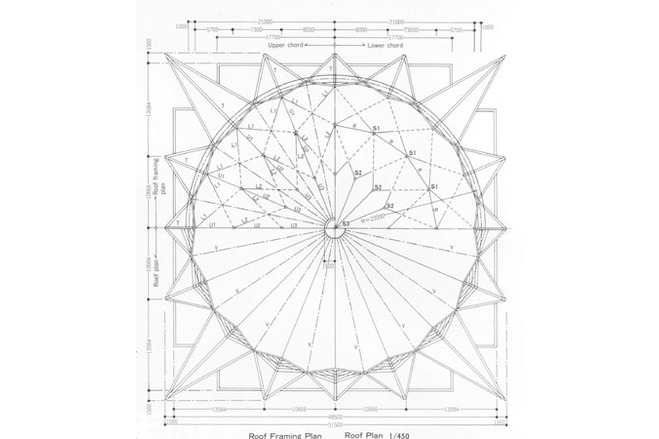
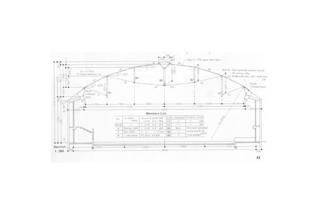
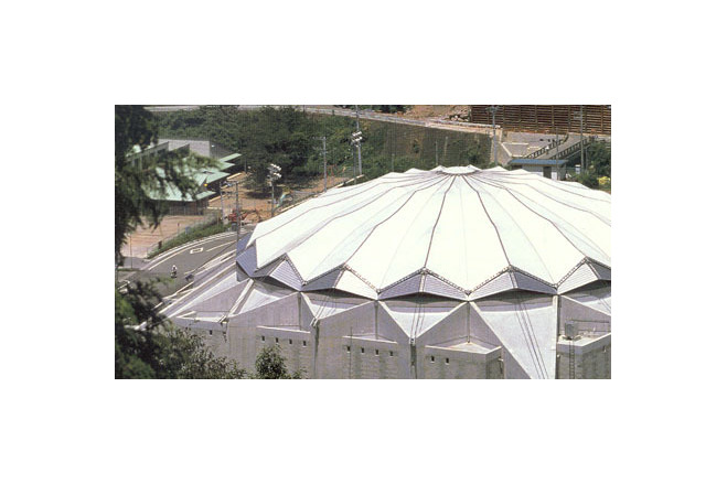
This multipurpose gymnasium was constructed to commemorate the 30th anniversary of the city's municipal administration. The large area of the gymnasium accomodates three volleyball courts surrounde by creatively designed bleachers which house two hundred audience seats.Prior to its construction a proposal competition was held by several design and construction firms in August of 1989. Fortunately, our tension dome proposal was the one adopted. It was the first tension dome ever built in Japan.Features of upper structural SystemThe gymnasium was comprised of two major structures : one was the upper structure which served as the tension dome, and the other was he system of substructural walls which supported the dome. The folded plate walls were made of reinforced concrete. The upper structure is still considered a new type of system, and it was developed by us explicitly for this project. It has been approved with special permission from the Minister of Construction. This system was named Tension Strut Dome system (TSD).The TSD dome has similarities to the cable dome, which was originated by Dr. D. Geiger in the U.S.A. there are, however, major differences:A. Cable domes use membrane material. They are constructed so that the rise of the domes are secured by a combination of diagonal cables and hoops. In contrast, the TSD dome is supported by a central lens-shaped cable-girder. This is suspended by a self-supporting tension truss which is anchored in cables below and a circular tension ring above that stabilizes the girder. In other words it is a new system that integrates two different structural systems.B. The Cable Dome system introduce tension to cable members in a continous way through various pulleys which are situated at the top of each of the posts. The TSD dome system utilizes tension in all of the upper and lower chords. These chords are situated independently and do not function with the use of any slip metal fittings.C. The tension to a cable dome, is introduced to nemerous diagonal cables in graduating stages. It is a step by step system that uses wedges to increase the tension by degrees. Tension can be introduced to a TSD dome by pulling the ends of the upper chord cables in basically one movement and at on time.The original configuration is therefore easily monitored and maintained, and it remains more stable as a whole.The TSD dome system can be appreciated as a realistic and practical design in the field of tension dome structures. Complexities regarding slip fittings technology and construction procedures used by cable domes have been improved with the development of this TSD system.This self-supporting tension strut dome is connected to its substructure through a complex of V-shaped steel beams. These beams are fixed to a reinforced concrete compression ring. It was difficult to solve the problem of the reception of the compression reaction force created from the large roof tension dome at the tips of the V-shaped beams.In principle, it is natural to accept such compressive reaction force by a ring truss formed by two rings. One would be an upper compression ring placed at the tips of the V-shaped beams where all of the compression reaction forces concentrate. The other would be a reinforced concrete compression ring placed on the substructure. However this method in actuality distorts the continous wave shape of the roof. The method that was therefore chosen directly connected the tops of folded plate wall and the tops of V-shaped beams with stays which continued along the line which extended form the upper chords.The compression reaction force can be therby be directly transferred from the chords to the V-shaped beams-then into the stays and on into the folded plate wall. With this method it has become possible to concentrate the compression reaction force onto the reinforced concrete compression ring which has been placed upon the tips of folded plate wall.
Description of the environmental conditions
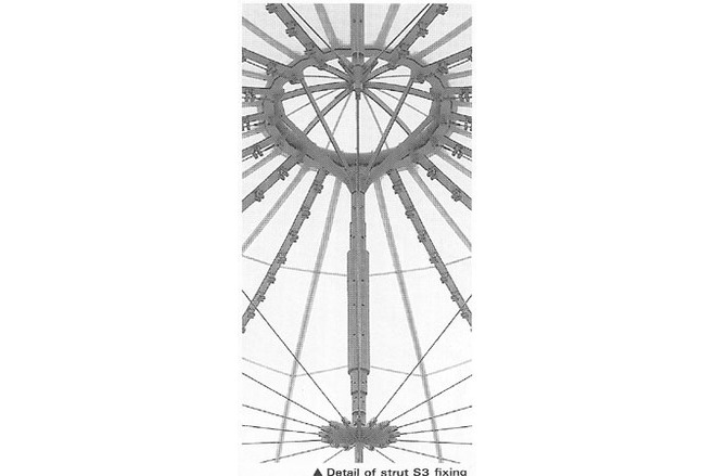
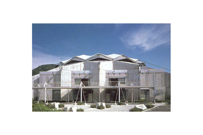
Examination of Material detailsAt first we had considered using wooden strut fixtures. Natural textured wood requires that pieces be taken from large trees. Glued laminated timber was therefore reinforced with steel and used. The appearance of wood is beautiful. Wood also has intrinsic properties, which naturally absorb large amounts of compression pressure and act as a resistance against the buckling of steel members.Theoretically, cable is most suitable to fulfill the key role in this tension system. Taking in to consideration the flexibility and elasticity of cable, during actual construction execution, it is fraught with vexing instability. During preliminary, temporary erection, using cable makes it especially difficult to maintain accurate positioning of the struts.So, after all, wire was only used for the upper chords, which need regular adjustment of its tensile force. Prestressed concrete steel bars have been chosen as lower chords because their length is much easier to control at the construction site. Sixteen lower chord members concentrate at the metal fitting of the lower end of the central strut. A fixture molded to receive these members is ideal but costly. A fixture of welded plates has a greater volume because welding margins.After much trial and error, a special "sesnet welding" became the selected course of operation. Through this process materialized a fitting as compact as one for which we'd hoped, and it was created at a cost that was satisfactory to our budget.The concentration of stress converges most powerfully at the tips of the V-shaped beams. This has presented the greatest challenge as well as the most complex problem to solve. At these points converge the ends of the upper and lower chords as well as the two spiral ropes, which connect the top of the V-shaped beams with the folded plate wall. In addition, supports have also had to be fixed there. The positioning of the weight of the temporary compression ring used for erection also had to be brought into consideration. Extensive and arduous experimetal research had to be under taken. Features of the Folded Plate Wall SubstructureThe substructure of the architectural concrete finish is composed of folded plate structural walls. Here, at regular points, the ends of sixteen radical lines have descended to connect from the apex of the roof. These are also the connecting locations of the sixteen equally divided pressure reception points of the compression ring, where the ends of sixteen valley lines are attached. The strength of compression ring and the force failing inward from the folded plate walls are so well balanced that they unitedly form a self-supporting structure. The balance from the intricate computations materialized throughout this enormous and economical structure has also resulted in a highly simplified foundation.
General comments, links
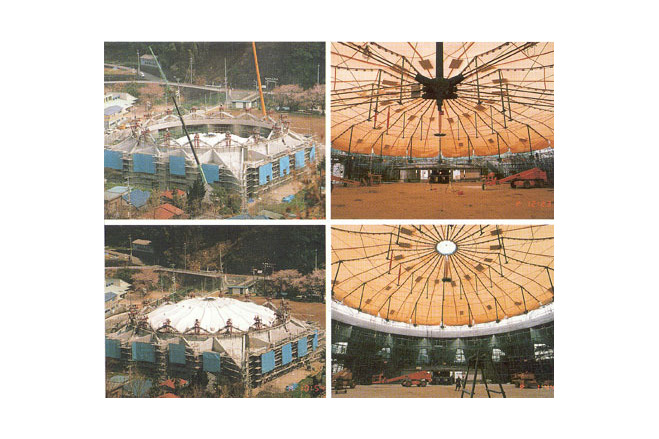
Adoption of Lift-up MethodThe grandness of a tension dome lies in its astonishing light-weight roof-generally less than one fifth the weight of any dome made from ordinary metal. Optimizing the advantages of its lightness the advantages of a one stroke construction method has been adopted. A previously fabricated roof structure is lifted up from the ground floor in a single, unbroken movement. The merits of the lift-up method are:A. No work is wasted. It is an extremely safe and also a quick procedure. Costs are reduced from the eliminating of unnecessary false work.B. The adverse effects of wind at the time of construction (the weakest point regarding regular membrane construction) can be avoided with the lift-up method.C. The fabrication of the roof structure on the ground and construction of the outer substructure can be done simultaneously.One design problem has been to find a satisfactory way to lift the roof structure that has been constructed on the ground level. The roof structure has a diameter of 43 m and must be mounted on a compression ring having a diameter of 42 m, smaller than the diameter of the roof structure.This problem was solved with a rotary device made into the minor parts of the V-shaped beams, which are attached to the compression ring. The V-shaped beams have been made to rotate. When lifting up the roof, the beams were turned outward. This device ahvew cleared the way with a 50 cm clearance on each side when lifting. After completing the lift-up the beams were then turned inward so that the roof could be mounted from above onto the beams.[Membrane Structures in Japan, Kazuo Ishii, p 72, 73, 77]
Amagi Dome the Amagi Yugashima Town Multi-Sports Center
Material of the cover
-
Cable-net/Fabric/Hybrid/Foil
Cable
-
Material Fabric/Foil
Fiberglass
-
Material coating
PTFE
Main dimensions and form
-
Covered surface (m2)
2298
-
Total length (m)
48
-
Total width (m)
48
-
Form single element
Anticlastic
Duration of use
-
Temporary or permanent structure
Temporary
-
Convertible or mobile
Convertible
-
Design lifespan in years
06-10
Involved companies
-
Architects
Keikaku Inc.
-
Engineers
Masao Saitoh
Structural Design Group Corp.
-
Contractors
Editor
-
Editor
Marijke M. Mollaert