Expo 1970 (Osaka): Fuji Group Pavilion


General information
-
Location address
Osaka
-
Location country
Japan
-
Name of the client/building owner
Fuji Group
-
Function of building
Exhibition
-
Degree of enclosure
Fully enclosed structure
-
Climatic zone
Temperate - cold winters and mild summers
-
Number of layers
mono-layer
Description
Scheme Outline
Created under the mottos of the "Total Experience" and "Pneumatic within Pneumatic", designers reached to create an exotic new space within a membrane structure which could be quite different. This type of structure converted the common style in to a new, remarkable, air-inflated type, composed of small inflated structures inside and outside of the main structure.
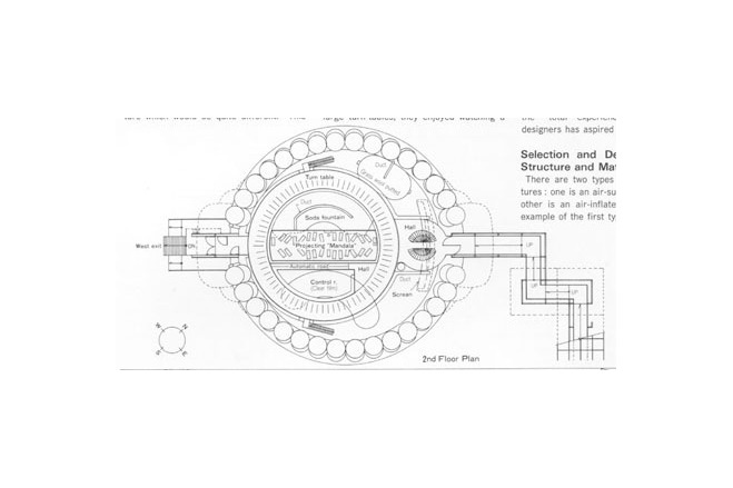
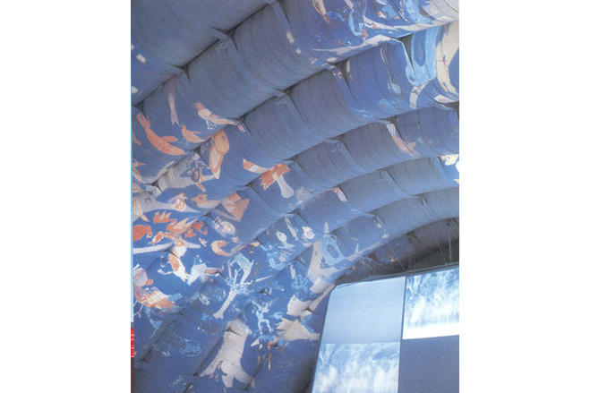
While visitors sat turning themselves on large turn-tables, they enjoyed watching a movie called "Mandala". This was still illmination of art which was projected to cover all of the interior surface of the pavilion. It was accompanied by music. The structure, machinery and equipment in unison provided the "total experience" for which the designers has aspired to contrive.
Selection and Development of Structure and Materials
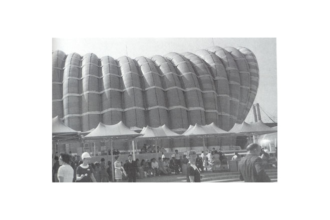
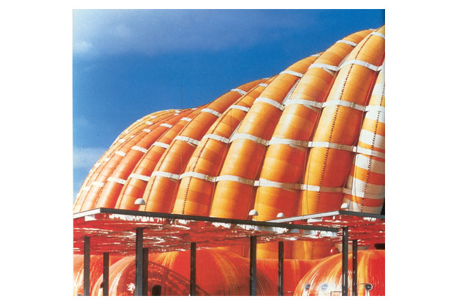
There are two types of membrane structures : one is an air-inflated type and the other is an air-inflated one. The typical example of the first type was Tokyo Dome. For the second type, the designers of an exhibition pavilion preferred to develop the open-air mood and decided to construct the "Air-inflated Tube Structure". This architecture is still the largest of its type in the world.
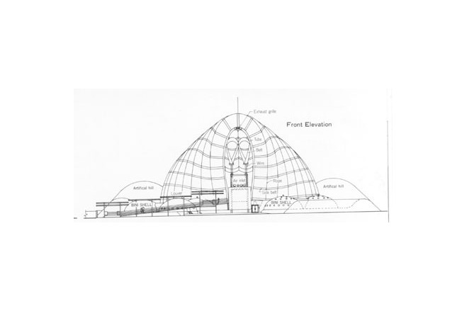
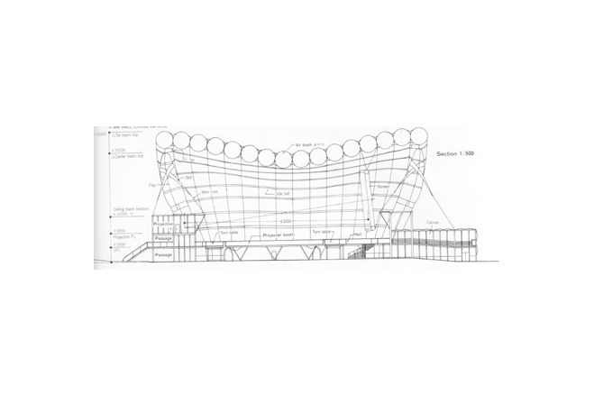
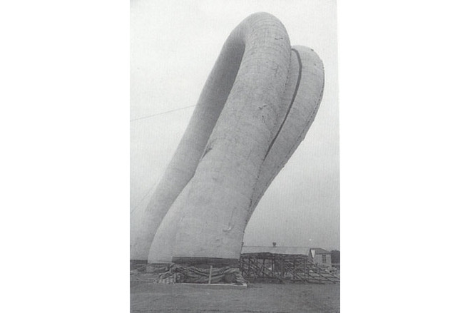
The shape was formed by 16 arch shaped tubes (each measuring 4 m in diameter and 72 m in length). They were arranged along the circumference of a circle having an outer diameter 50 m. The air-tubes, standing in a row, were bound together with horizontal belts measuring 50 cm in width. Even tough it held an organic shape, it could still be made into a three dimensional geometric form.
An air-inflated membrane structure is comprised of pure tension structures, making use of the balance of the compressed force of air and the tensile force of the membrane material. It maintains its safety standards by human or mechanically induced changes within its structural strength to cope with and counter varying external forces. It is a structure that has to be continually steered and operated, sometimes in strong contrast in opposition to the state of the existing building which is based on static dynamics.
At the time this pavilion was built, properties of internally air-supported membrane structures were fairly well-known, but very little was documented concerning air-inflated types. There existed no precedence nor accumulation of technology.
The author of this particular article concerning the Fuji Group Expo Pavilion, along with his team, had to precisly calculate each detail of the new plan in an extremely limited time span. Such calculations included material development, grasping of the properties of air-inflated structures, creating exact structural models, establishing analysis methods, designing details, examining forms, determining appropriate fire prevention measures, etc. All such research and development was performed quickly. When fire-prevention tests were successfully performed on two full-size tubes, apprehension dissipated and construction forged strongly ahead. The preliminary fears and tension we then had are still vivid memories today - twenty years later.
A large number of experimental membrane materials, which would grant freedom from past regimentations, were tested for use for the final structure. Results from the studies were considered, and special attention was given to manageability in handling. A tube-like canvas was developed. It was made of Vinylon fabric (monoaxial rupture strength 200 kg/cm) and was double layer, pasted together with neoprene adhesive. Its surface was hypalon-treated, and its lining was a coating of polyvinyl chloride film (tarpaulin), which is used for air-tightness. The final product of the membrane material was 4 mm in thickness and 5 kg/m² in weight.
Description of the environmental conditions
Maintenance and Adjustment of Interior Air Pressure
Pneumatic membrane structures are built to withstand external forces by the tensile force of the membrane. The tensile force is introduced from the combined difference of air-pressure that exist inside and outside of the building.
The arched air beams (tubes) of this pavilion were designed to keep its air pressure at 0,08 positive against the external atmospheric pressure registered under usual conditions. A positive pressure of 0,25 was used to counter-act stormy wind conditions . The positive air pressure standards required for air tubes have been 10 to 40 times higher than those required for normal air-supported structures.
Because of the increased air pressure, air-tightness was extremely important. Even if beams were perfectly airtight and had 0,1 positive air pressure, they still could not withstand the lowering of the air pressure which resulted from lowered atmospheric temperatures. A practical solution allowed a limited air exhaustion and kept a continual flow of air blown into the tubes at all times. This method maintained the air pressure at a constant level. The control mechanism that was required displayed a continual data feedback showing variations in the air pressure inside the beams. These variations were caused from external factors. The device automatically made readjustments in the air supply to maintain constant pressure in the tubes. A programmed exhaust system was much preferred to natural and uncertain leakage.
Under turbulent weather conditions the total volume of air needed to fill all of the arches of this pavilion was approximately 64 m³/min. Two blower units, each having a capacity of 2700 mm Ag at 115 m³/min (equaling a total capacity of 230 m³/min) were installed. The safety factor was set at 3,6. The air control safety system adopted operated its valves by air signals.
One of the greatest threats of security to pneumatic structures is excessive air pressure. To avoid such a problem, a fall-safe system is required. For this particular project, a safety system was devised by making use of a pond set reservoir which surrounded the pavilion and which was not to exceed 0,25 air pressure.
Erection
Air beams were erected in this sequence. First, the central beam was erected; then, one by one, others were erected equally in both directions. A P&H crane was used to help with the erection by supporting the center top of each tube. Movable stages, including joining beams and setting belts, were converted effectively form truck cranes. A single beam weighed approximately 4 tons. It took five days to inflated one beam from a deflated position.
[Membrane Structures in Japan, Kazuo Ishii, p 94, 95, 98, 99]
Material of the cover
-
Cable-net/Fabric/Hybrid/Foil
Foil
-
Material Fabric/Foil
Vinylon
-
Material coating
CSPE
Main dimensions and form
-
Covered surface (m2)
3369
-
Total length (m)
50
Duration of use
-
Temporary or permanent structure
Permanent
-
Convertible or mobile
Convertible and mobile
-
Design lifespan in years
00-05
Involved companies
-
Architects
Yutaka Murata
-
Engineers
Mamoru Kawaguchi
-
Contractors
Editor
-
Editor
Marijke M. Mollaert