Top Golf Club House


General information
-
Home page
http://www.topgolf.co.uk
-
Location address
World Golf Systems Group plc, Axis 4 Rhodes Way Watford Herts WD24 7AB
-
Location country
United Kingdom
-
Year of construction
1999
-
Name of the client/building owner
World Golf Systems Group plc
-
Function of building
Entertainment & recreation
-
Climatic zone
Temperate - cold winters and mild summers
Description
Buro Happold was appointed by the contractors to undertake the conceptual design, structural analysis, detailed design and patterning for the Top Golf clubhouse in Watford. The building shape originated from some sketches by S & P Architects. The design also required the membrane to be supported by masts and for the membrane roof to have a partially glazed area to comply with daylight requirements. It was especially challenging to provide glazed areas within the membrane surface, as membrane structures are deflection sensitive.
Similar shaped structures to that required at Top Golf had been built before, with the lenses built as heavy bending elements, carrying the high tensile forces induced by the membrane to a few support cables. Furthermore, visually disturbing cables were used to deal with the uplift forces on the lenses under wind suction caused by the lack of curvature in the membrane shape.
The specific challenge on the Top Golf project was to prevent the use of interior cables and to minimise member sizes of the lenses. A solution was found by pre-stressing the lenses down against a series of thin hanger cables to the perimeter struts.
Description of the environmental conditions
The fabric roof will give the interior a semi-open environment. The transparent lens will allow light to enter the through the roof and so will the semi-translucent PVC fabric.
General comments, links
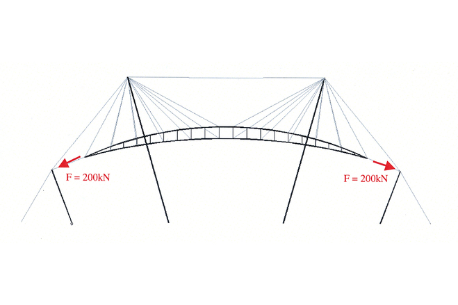
The building with the dimensions 35m x 45m is covered with a membrane structure. Three approx 22m high masts support the membrane roof vertically. The membrane is attached on a lens shaped virendeel steel frame. The steel frame for glazing support is held up by a series of cables and hangs from the masts. Two cables attached on the end of the lens secure the position of the lens side ways. The membrane is pre tensioned against the boundary and valley cables. The boundary cables are supported by struts and tie down cables. On the longest side of the building the boundary cable is attached directly onto the adjacent Driving Range. The masts are stabilised by the hanger cables and additional guy cables.
The installation procedure was carried out in 10 hours. Pre-installed masts lifted the lenses, with membrane attached, off the ground. No cranes were used, so to enable this lifting procedure, the installation process was analysed computationally and the lifting equipment was force controlled to minimise bending moments in the not yet stabilised long and slender lenses. Surveying the connection points prior to installation eliminated the need for many adjustment devices on the cables.
Are all Membrane Stuctures Similar?
Material of the cover
-
Cable-net/Fabric/Hybrid/Foil
Foil
-
Material Fabric/Foil
Polyester
-
Material coating
PVC
-
Weight (g/m2)
1500
Main dimensions and form
-
Covered surface (m2)
1500
-
Total length (m)
45
-
Total width (m)
35
Duration of use
Involved companies
-
Architects
S & P Architects
-
Engineers
Buro Happold
-
Suppliers
SERGE FERRARI