Government Stadium Hong Kong


General information
-
Location address
Hong Kong
-
Location country
China
-
Year of construction
1994
-
Name of the client/building owner
Royal Hong Kong Jockey Club
-
Function of building
Stadia
-
Degree of enclosure
Fully enclosed structure
-
Climatic zone
Tropical - hot and wet all year
Description
Design
A lack of international-standard sports facilities have long been a problem for Hong Kong; almost six million inhabitants on 1000 km² inevitably leads to other priorities in land use. The solution , as often in Hong Kong, came from the Royal Hong Kong Jockey Club, which operates the only legal betting franchies in the Terretory. It commisioned proposals for a modernisation of the Government stadium in So Kon Po, south of Causeway Bay on Hong Kong Island. Four schemes were investigated, two renovation scgemes and two renewals. Each of these preliminary designs were analysed on a cost-benefit basis taking into account design, construction, marketing and financial factors.
Brief
40000 seats, 75 % covered by a roof
- Stadium designed for football and rugby, but without an athletics track
-Provision of 50 corporate boxes, each with its own catering facilities
- Facilities for major pop concerts
- No underground car park
- Construction scheduled so that the annual Rugby Sevens Tournament could take place
- Construction period not exceeding 3 years
Tendering
In the tender documents the construction period was set at 36 months. For the structure in-situ concrete frames and slabs with precast concrete bleachers wre anticipated, for the roof two main arches spanning 240 m north to south with a rise of 55 m. Steel trusses at 6 m centres were to span between the arches and the upper ege of the precast concrete rakers. Dragages et Travaux Publics also offered an alternative design (beside their regular offer) with a construction period of only 24 months and a considerable cost discount based on a modified structural concept:
- The secondary beams and floor slabs of the concourses were precast concrete elements; and
- the steel trusses of the roof came at 12 m centres instead of 6 m.
Their offer was conditional on the design team being under the direction of the contractor and not the architect, so that the working drawings could be prepared in a sequence and without communication problems. After assessment of the offer the contract was awarded to Dragages.
Development of the roof design
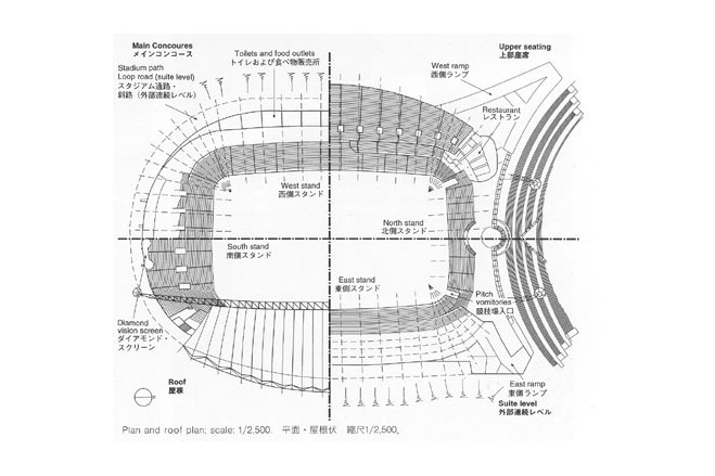
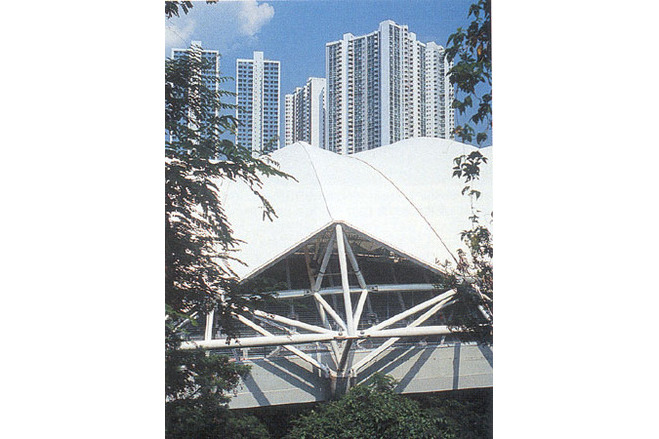
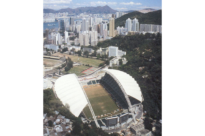
The project was subject to decisive external constraints and an extremely tight time schedule. The roof form was determined largely by the topography of the steep So Kon Po valley, also the shape and massing of the stadium was supposed to reflect its situation in the valley.
In the attempt to have the structure follow the roof edge, almost by chance the concept of a wide-span truss arch emerged alongside other variants (a curved space-frame roof was also explored). This expressive form became further emphasised by enlarging the arch span to the total length of the stadium. Thereby the arches developed into major design element at the entrance. For architectural reasons the arch arrangement had to be symmetrical.
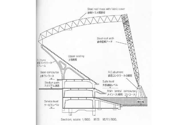
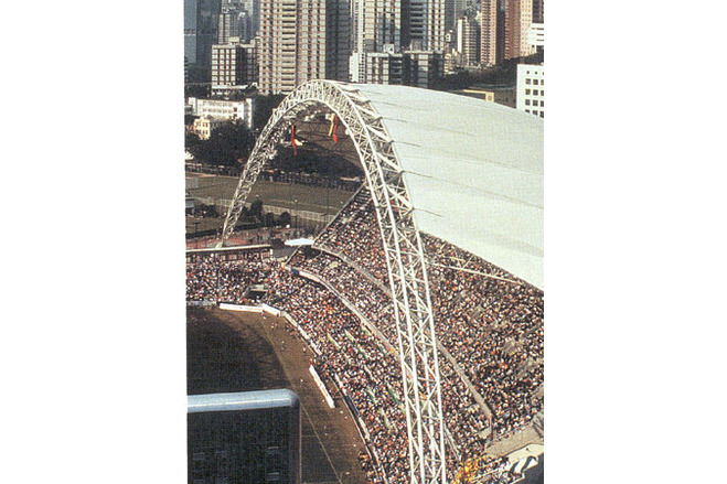
A rock slope in the valley, on the far side of the loop road, offered a meaningful abutment position. The arch then had to rise steeply to provide vihicle headroom, and becoming cycloid in a plane 12° to the vertical. Trusses span from the arch to concrete rakers at the top of the stands. The roots of the arch were detailed as pins, which is more an architectural feature than a structural necessity.
Description of the environmental conditions
Structure
The main arches are two-pin trusses with a square cross-section (3,5 m x 3,5 m), which are inclined at 12° to the vertical. The chord membera are steel tubes (Ø 406 x 12,5 mm, Ø 406 x 16 mm and Ø 406 x 20 mm); as membrane connection a halved square hollow section (Ø 400 x 400 x 12,5 mm) is welded on. The length of a arch truss module is approx. 5 m; they have been manufactured in pairs, so that one arch is made up 24 pairs of straight units. The web members, verticals, horizontals and diagonals are CHS (Ø 193 mm to 273 mm).
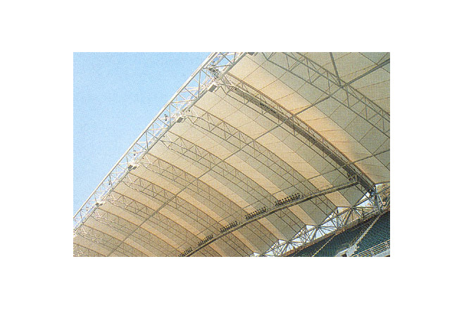
The curved secondary roof trusses are hip frames pin-supported at the rakers ends. They span between 40 m and 55 m and have a three-chord section 3,5 m deep. They are connected to the arch by stainless steel bearing pins. At the support on the rakers a vertical truss frame element acts as a column.
The valley cables (Ø 80 mm), midway between the secondary beams, are prestressed against the horizontal truss members and a simple truss element in the upper plane of the arch. These horizontal trusses transfer their compression loads into the secondary beams; the horizontal components of the valley cable forces are thus balanced at the roof plane.
Load Assumption
The value of the wind forces was finally to be confirmed in wind tunnel tests. These were carried out with a standard typhoon windspeed as described in the HK Code. An aeroelastic wind tunnel model was built to explore the interaction of the roof structure with the wind. The resulting wind loads were higher than expected, the critical load case was the northerly wind direction parallel to the arch.
This made it necessary to reinforce the structure and the membrane and also resulted in an increase of the design loads for the glazing.
Bracing
Along the upper edge of the stands the structure is stiffened through cross bracing. The vertical elements of the roof trusses are connected by truss members and thus stabilise the secondary trusses. They carry the wind loads in the longitudinal direction of the roof and transfer them into the stand structure.
The roof girders are connected with each other by structural elements (Ø 273 x 16 mm, Ø 273 x 20 mm, Ø219 x 12,5 mm) proceeding parallel to the arch and are thus braced, to provide lateral stability and to resist the horizontal wind forces from the roof membrane . These structural elements are anchored in the last roof girders, equipped with an additional cross bracing (Ø 355 x 16 mm) between the bottom chord members, whereby the horizontal forces are transferred to both sides, into the arch and into the cross bracing along the top edge of the stands.
General comments, links
Membrane
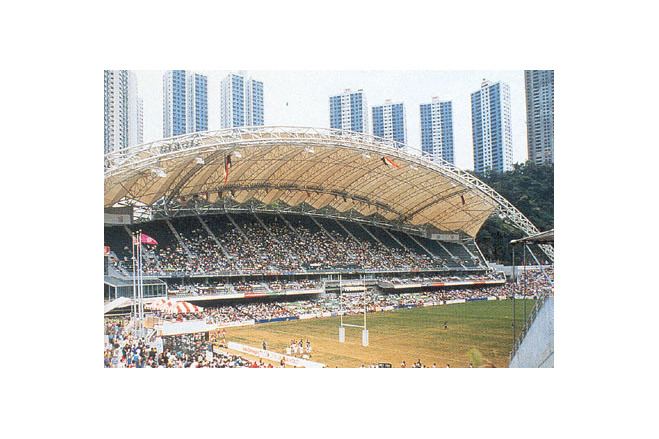
The covered plan area of the roof is gigantic 8000 m². To minimise the self-weight of the structure, a PTFE-coated glass fibre fabric (in the end a Shearfill membrane supplied by Chemfab) was proposed as a roof membrane. This kind of covering was new for Hong Kong in this scale, but was considered appropriate by the authorities and the client.
On both sides the roof was subdivided into five large panels, covering three roof bays each. The membrane is a lat saddle shape between the arch upper chords and the valley cable. Next to the arch it is nearly flat, increasing its curvature towards the outside edge. The membrane sag relative to the valley cable corresponds to the depth of the roof girder.
The valley cables together with the edge clamps serve for the prestressing of the membrane. Under wind load they transfer the major part of the wind uplift.
Along the edges the membranes are connected by a series of clamping plate strips, while they are not fixed at the upper chords. Along the roof girder they are clamped with aluminium U-sections, boltropes and Neoprene padding onto an aluminium base plate, serving as construction aid. The plate is turn bolted onto a cold-worked sheet metal section, weled onto the upper chord of the roof girder. Along the edges at the main arch, which carry less load, a similar detail is used, where the U-section is replaced by a clamping strip made from aluminium flat.
In the end bays the membrane edge is formed by an edge cable, thus avoiding bending of the edge girder. There the membrane is clamped with clamping plate strips and boltrope and joined by stainless steel U-straps (Fl 50 x 5, a = 400 m) with the edge cable (Ø 80 mm). A splash plate is fastened parallel to the clamping plate strip as a shallow gutter.
Construction
First year
Demolition of the old stadium began the day after the Rugby Sevens Tournament of 1992. Only the old pavilion was retained to house the changing rooms for the 1993 games. In the first year the entire podium structure was erected where in the following summer, 1993, the Rugby Tournament took place. Construction resumed after the event.
Second year
The main tasks of the second year were to erect the roof, complete services and finishes and lay the permanent pitch along the edges. Roof girders and arch sections were assembled on trestles on the pitch and welded up from components, before the last layers of corrosion protection were applied. Each arch was assembled by crane masts in four sections supported at the joints, and simultaneously a working platform was provided, from where the in-situ splice welds were made.
After the final coat of paint for the steelwork the roof membrane was assembled. The panels were delivered from Australia and mounted on a scaffolding above the rear bracing. Light cables were attached to the free edge and the membrane pulled towards the arch by tirfors fastened at the truss chord. The loose, deployed fabric was gradually hauled to its connection points via threaded bars connected at the edge clamping strips. After all the clamped edges were fixed, the valley cables were lifted up from the pitch, the rear pin installed and the pre-tension applied by a jack on the arch. Following erection of the roof, work could start on the construction of the permanent pitch and installation of the seating.
[Soft Shells, Hans-Joachim Schock, p124-127]
Hong Kong Stadium
Roof of Government Stadium, Hong Kong
Material of the cover
-
Cable-net/Fabric/Hybrid/Foil
Cable
-
Material Fabric/Foil
Fiberglass
-
Material coating
PTFE
Main dimensions and form
-
Covered surface (m2)
16000
-
Total length (m)
55
Duration of use
-
Temporary or permanent structure
Temporary
-
Convertible or mobile
Convertible
-
Design lifespan in years
00-05
Involved companies
-
Architects
Hellmuth, Obata & Kassabaum Inc.
-
Engineers
Ove Arup & Partner Hong Kong Ltd.
Editor
-
Editor
Marijke M. Mollaert