Airport Salzburg (Austria)


General information
-
Location address
Salzburg
-
Location country
Austria
-
Name of the client/building owner
Salzburger Flughafenbetriebsgesellschaft m.b.H.
-
Function of building
Airports
-
Degree of enclosure
Fully enclosed structure
-
Climatic zone
Temperate - cold winters and mild summers
-
Number of layers
mono-layer
Description
Increased traffic at Salzburg airport in recent years made it necessary, and economically possible, to carry out a reorganisation and redesign of the 'landside, i.e. the side connected with ground traffic, to make it more user-friendly and to improve the traffic system. The principal features of the improvement scheme were a six-storey, 300-m long car park and the reorganisation of the airport forecourt with a generous roof, covering four lanes and smaller roofs over the footpaths between the car park and the service building.
Requirements
The roofs had particular requirements and therefore demanded special solutions: As the forecourt of the airport, with its roads, parking areas and footpaths is used rather heavily, restraints emerged for the desired roof constructions and technical requirements, such as differing clearance heights for car and pedestrian traffic and safety distances, which had to be observed. The goal of the architects was to develop a roof shape, which, in addition to its function as weather protection, would provide some visual orientation on the forecourt and generate a light, friendly and positive atmosphere. The present concept was named first choice in the limited competition because of its dynamic membrane shape and a form language corresponding to the movement of flying. It was later chosen for execution. The project consists of four principal parts:
1. A large canopy (110m x 25m) as roofing over the drop-off area in front of the entrance of the existing service building.
2. A covered pedestrian zone (350m x 2.5m), along the parking garage.
3. The 'links' between canopy roof and pedestrian zone, consisting of three parts (one 18m x 7m and two 45m x 7m).
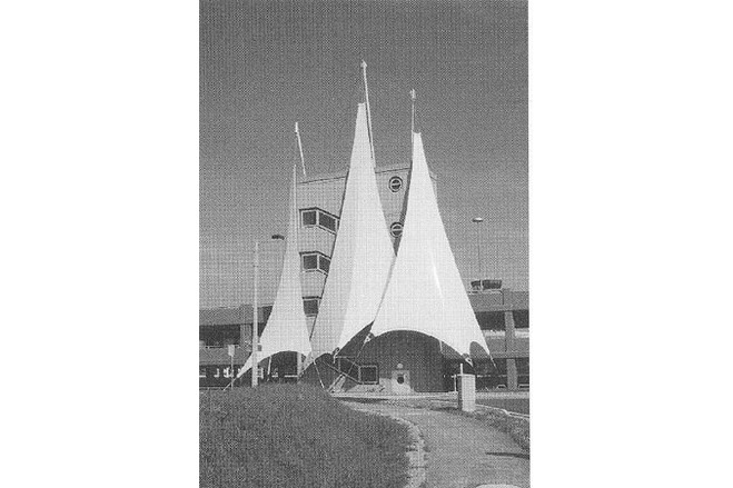
4. A 'Logo structure' for the parking garage, consisting of three sails mimicking the nearby Alpine mountains.
The following wish list refers to the desired properties of the roof cover:
- A cover, which is translucent but avoids glare in strong sunlight to provide shading, without making it too dark;
- Dirt on the surface should not be visible from below;
- Easy maintenance and cleaning and good durability;
- Good resistance to hail and snow and noiseless when it rains;
- A manageable technology in detail, with a high degree of prefabrication and a short assembly period;
- Cost effective and economical construction.
Design
All four structures exhibit a dynamic steel and membrane form and careful detailing.
The canopy roof swings up, opens towards the car park and draws the visitors into the service building.
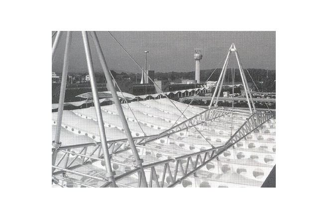
The pedestrian zone roof moves in waves along the parking garage.
The large undulations join the car park ('the ground') with the service area ('the air/ flight'). With their dynamic shape they seem to 'fly' over the road with ease at the required clearance height of 5 m.
The logo, as the highest point of the roof shape, serves as goal and guidepost for the travelers and visitors arriving by car, and conducts them into the car park. The design represents three snow-capped peaks.
The roofs are pure rain shelters and have no additional function.
Description of the environmental conditions
Structure and membrane forms
All four structures are mechanically tensioned membranes with different geometries:
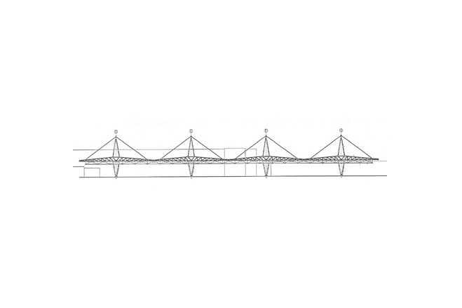
The canopy roof consists of linearly added arched surfaces and corresponds to the type of the arch arcade; it consists of saddle surfaces, rectangular in plan, formed by parallel arches and intermediate straight edges. The links and the pedestrian zone are wave-shaped ridge and valley forms (wave surfaces).
Substructure
As a counterpart to the tensile structure, the works above the substructure are primarily in compression. As a compression system some unusually curved and formed steel tube structures are used, and four mast trestles carrying steel truss girders suspended from them. The link structures have similarity with the spars of a ship.
These three structures have no guys or tension foundations, as the membranes are braced by steel frames at roof level. The steel compression structure transfers the forces to the ground via compression pad foundations. The logo is the only tensile membrane guyed via steel masts and compression struts.
Canopy roof
The primary structure consists of four mast trestles of circular tubes, with four triangular truss girders in two rows suspended from them. These carry the 24 main girders of the membrane roof, curving slightly upwards and perforated with circular web openings. Their bottom chord consists of a horizontal H section, which simultaneously serves as gutter, as anchor point for the membrane and as prestressing support for the transverse arch girders. The arch girders are made from circular tubes with a horizontal steel tube tie separately connected with a pin. The arches are held laterally by a stabilising cable running in the longitudinal direction of the membrane and anchored in the end bays at the longitudinal girders by means of two bifurcating cables.
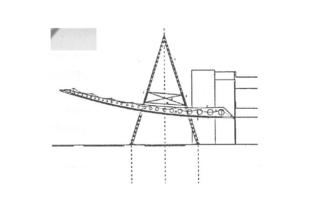
Links
The roof consists of two similar parts of different lengths. A slightly upward curving hollow box girder with square cross section is supported by four twin columns of circular tube, which together with the connecting elements form a gable frame. The columns are fixed at reinforced concrete foundations. Cantilevering from the hollow box section to both sides are tapering members carrying on the outside a curved wave-shaped edge girder made from a circular tube, on which the roof membrane is fixed.
Pedestrian zone
The roof covers the pedestrian area along the car park and consists of a continuous, undulating membrane surface of rectangular elements in plan, with a wave-shaped front and a straight rear edge. Tube columns encastrated in the foundations carry curved cantilevers with a raised gutter from a cold-worked C-section, into which the membrane is prestressed. The front edge is formed by a steel tube in which the membrane is anchored.
Logo
Three four-point sails each forming an upright triangle represent the peaks of the Salzburg Alps. For architectural reasons they consist of planar membrane surfaces, which are not in fact sensible structural elements at this size, because technically they could not be realised without extreme difficulties. Therefore they had to be modified into an anticlastic (saddle- shaped) surface by a ridge cable lying in the membrane surface and stabilising the sails. They are anchored at their top by a short tubular mast and two guys connected in the roof of the car park's stair tower. On the ground they are anchored in four reinforced concrete foundations and the walls of the building.
General comments, links
Roof membrane connections
The roof membrane of all four buildings consists of PVC-coated polyester fabric type II with a PVDF topcoat.
Canopy roof
At the bottom chord of the transverse girder the membrane is connected by welded-on circular steel keys and short tube sections inserted into a membrane sleeve. For the prestressing of the membrane the arch girders are jacked up from a jacking seat and fastened adjustably by bolts to steel plates welded onto the main girder. Along the building the roof membrane is held by a straight, rigid element - a gutter section similar to the connection along the transverse girder - and at the front edge of the roof by an edge cable.
Links
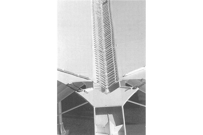
Along the edges the membrane is connected by welded-on circular steel keys and short tube sections inserted into a membrane sleeve. Where necessary, a membrane gutter proceeds along the membrane edge clamped onto fixing brackets. To avoid a prestressing detail with a complicated geometry, the membrane was fastened and tensioned by a lacing parallel to the central girder: over the central girder a welded steel sheet valley gutter is placed, into which the membrane is laced around a circular tube lying in the gutter and fastened to welded-on steel plates. To enable the lacing, the membrane edge is equipped with a boltrope and a row of eyelets. At the narrow sides the roof skin is held through edge cables. On the outside edge either a 'rain boltrope' is fixed, i.e. a round foam rubber piece welded into a membrane sleeve, or a membrane gutter is clamped onto the snow grid.
Pedestrian zone
Above the tube cantilever a sheet metal prestressing gutter is connected, with prestressing bolts welded on. Two adjacent membrane panels, furnished with boltropes, are held with steel-flat clamping strips and prestressed into the gutter below with nuts.
The membrane connection along the front edge is similar to the one along the sides of the previous roof, i.e. short tube pieces in a membrane sleeve. At the back edge the membrane is led over a horizontal CHS and anchored behind by rectangular tubes inserted into membrane sleeves and held by a prestressing bolt arrangement; around these bolts the membrane is cut out in a circular shape.
Logo
At the membrane corners bent triangular corner plates with a central opening join the oncoming ridge, edge and guy cables with each other. The edge cables run in membrane sleeves reinforced with a webbing. They cannot be prestressed separately, but are connected directly at the corner plates through fork fittings. Valley cables and guys have a swaged, threaded fitting. The webbing strips are connected adjustably through light fork turnbuckles.
[Soft Shells, Hans-Joachim Schock, p141-144, 146]
Airport ,A-Salzburg
Neuf/Nieuw
Airport, Salzburg, Austria
Material of the cover
-
Cable-net/Fabric/Hybrid/Foil
Cable
-
Material Fabric/Foil
Polyester
-
Material coating
PVC
Main dimensions and form
Duration of use
-
Temporary or permanent structure
Temporary
-
Convertible or mobile
Convertible
-
Design lifespan in years
00-05
Involved companies
-
Architects
IF Ingenieurgemeinschaft Flächentragwerke
-
Contractors
Editor
-
Editor
Marijke M. Mollaert