Millennium Dome in London


General information
-
Location address
London
-
Location country
United Kingdom
-
Year of construction
1996
-
Function of building
Entertainment & recreation
-
Degree of enclosure
Fully enclosed structure
-
Climatic zone
Temperate - cold winters and mild summers
Description
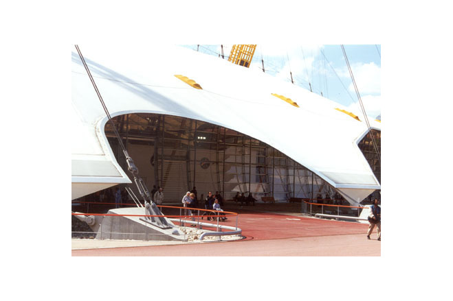
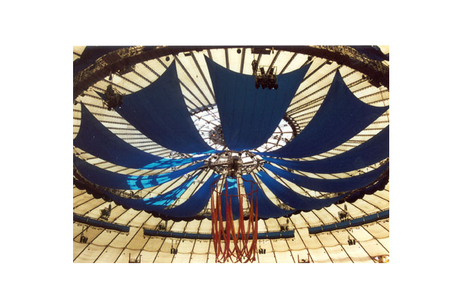
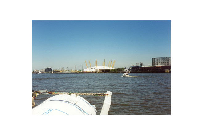
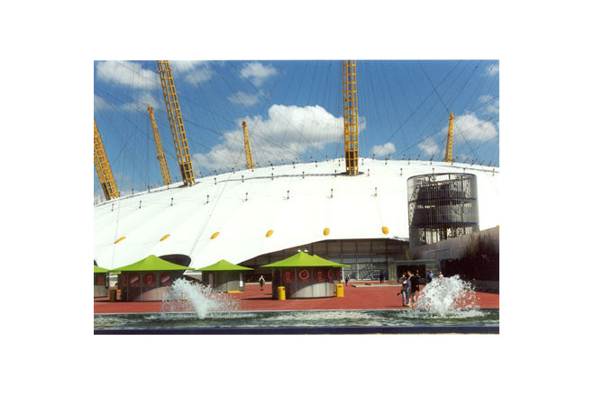
As part of the programme for the millennium celebrations, a contaminated gasworks site, which had been unused for 20 years, was rehabilitated to accommodate this huge domed tent - the largest membrane structure in the world, with a diameter of 365m and a height of 50m. After the New Year's party held there at the beginning of 2000, the dome was converted into a theme park with a number of pavilions designed by British architects. The pavilions are laid out in a circle and contain various exhibitions. At the centre of the tent is an area for dance and acrobatic performances. In January 2001, the dome will be taken over by a new concern that will present other attractions. The estimated life of the structure is at least 25 years.
[Detail 6/2000, Membrane Construction, p 11018]
The Millennium Dome was designed and built between 1996 and 1999 to house the Millennium Experience exhibition. The idea was the outcome of an interaction between the designers, Imagination, and the architects, Richard Rogers. It was then taken up by the engineers at Buro Happold, who developed the concept of the tensioned fabric-and-cable roof. The structure has now become the icon for the millennium celebrations in London.
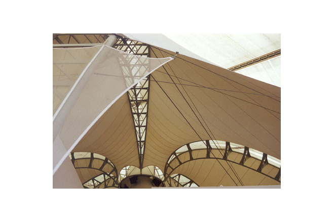
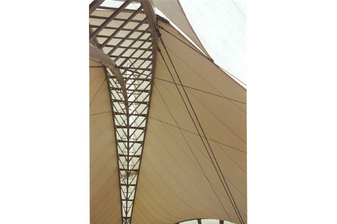
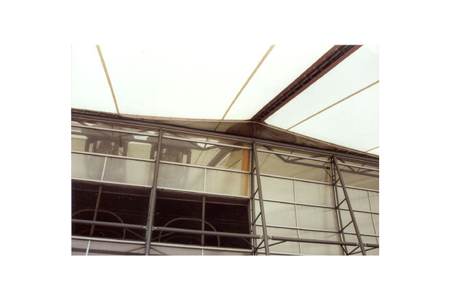
The dome roof design
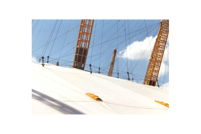
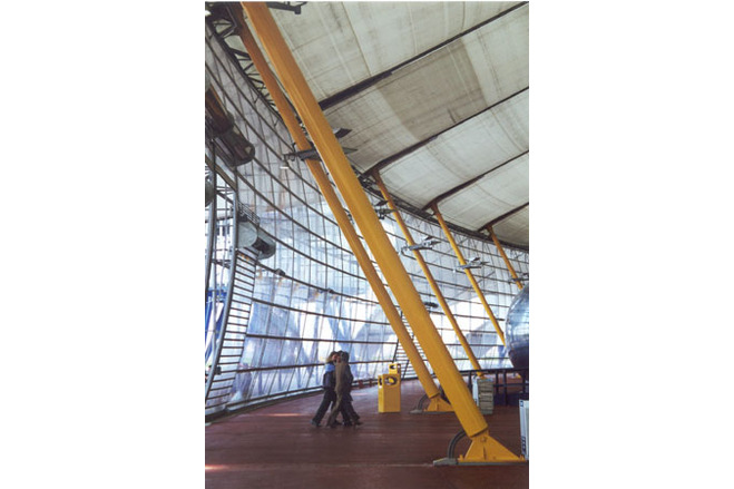
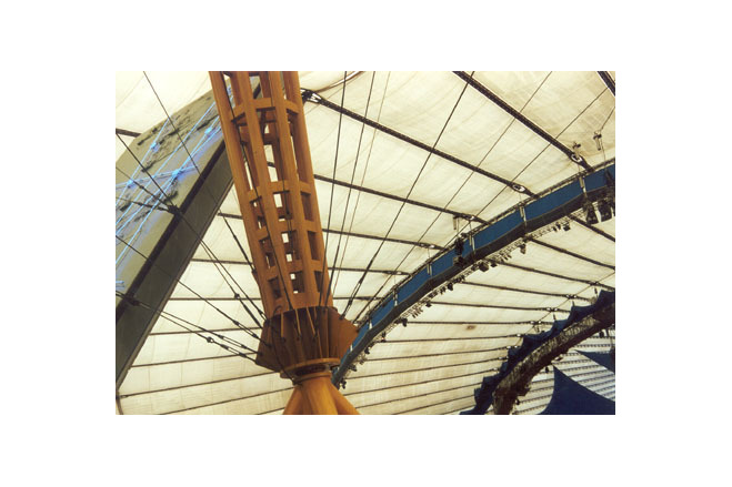
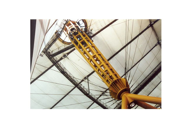
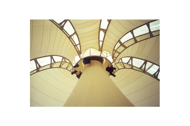
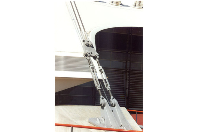
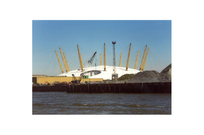
The innovatory structural concept for the roof of the Millennium Dome is seemingly simple. Arranged radially over the surface are 72 tensioned steel stringer cables in pairs of 32mm diameter steel spiral strand. The stringers are supported at a radial spacing between 25 and 30m by an arrangement of upper hanger and lower tie-down cables set out around the twelve 100-metre-high primary steelwork masts. Circumferential cables keep the stringers on their radial lines.
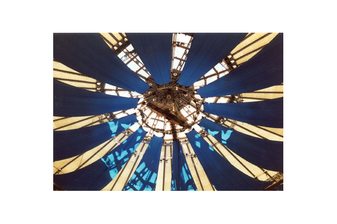
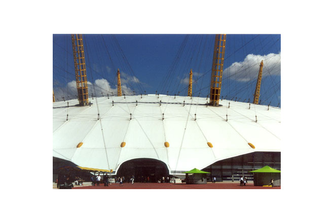
Tensioned PTFE-coated fibreglass fabric was used as cladding. The tensioned cables are straight, and the fabric is basically flat. They both carry the loads by deflection accompanied by an increase of tension. This concept is simple, but there are dangers associated with the deflections, particularly that of ponding caused by snow or heavy rain. When loaded by wind or snow, the upper hangar, the lower tie-down and the radial cables carry the loads from the fabric down to the ground. The forces from the primary radial cables are collected at the centre by a 30-metre-diameter cable ring. This was constructed with twelve 48mm diameter cables to provide safety against failure of any single one. At the perimeter, the radial cable forces are collected by 12 curved boundary cables and taken to 24 anchorage points.
Tension structures rely on the shape of the stressed surface for their performance under load. Forces are resisted by the tension and the curvature: the greater the curvature, the smaller will be the tension needed to resist a given load. The radial stringer cables are prestressed to 400kN/line, and the fabric is prestressed to 4 kN/m.
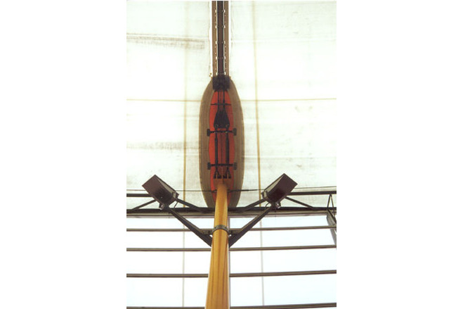
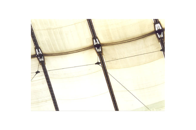
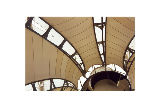
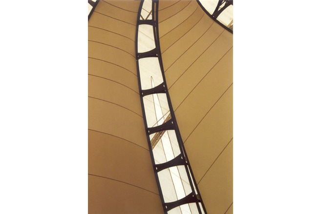
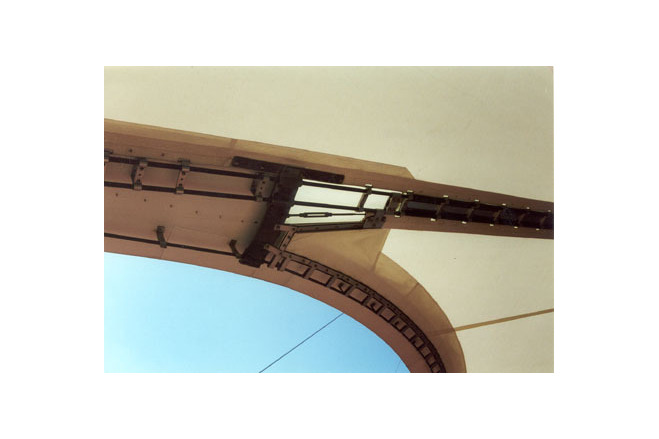
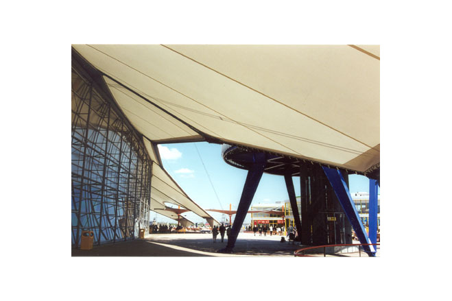
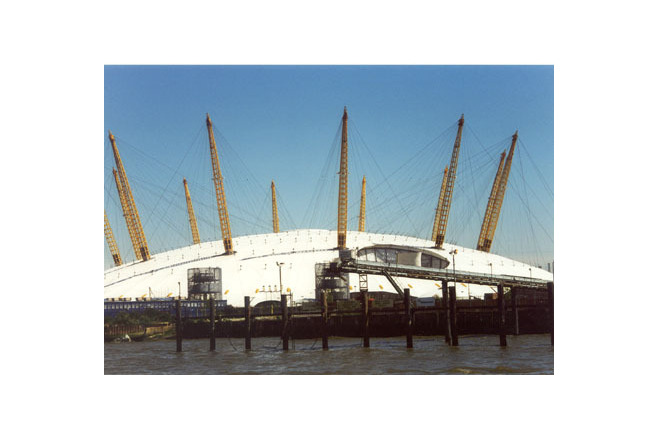
The shape of the dome roof, with tapering segments, has the advantage that the slope of the fabric panels increases with the span. If the circumferential cables were in contact with the surface of the fabric, however, their hard lines would cause dams and potential ponding. It was necessary, therefore, to remove these cables from the surface. This was achieved by raising the circumferential cables above the surface by means of rigid members (wishbones) and connecting them to the nodes with criss-cross cables.
Description of the environmental conditions
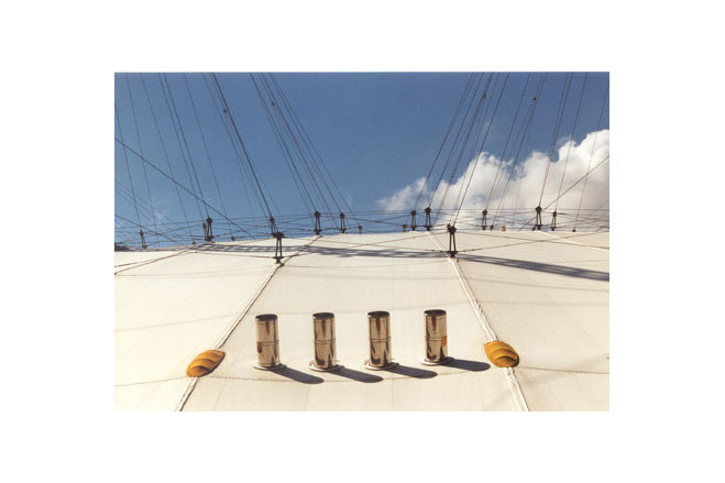
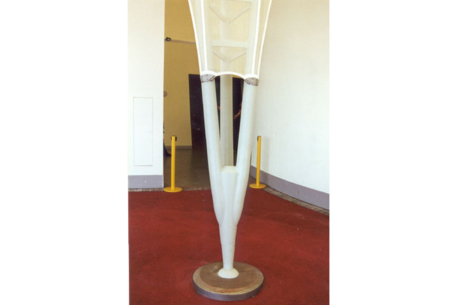
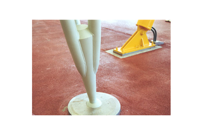
Structural detailing
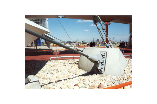
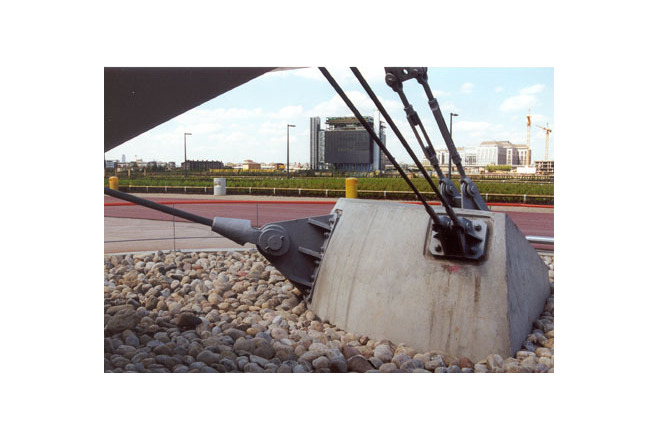
With cable structures, it is essential that the details respect the system lines and system points of he cables and their intersections, as well as the likely movements of the cables at the connections. If the radial cables were continuous through the node points, the flexing at those points would cause the cables to fail prematurely in fatigue. At every hangar, therefore, the radial stringer cables are terminated and connected with barrel-shaped pins to the nodes - an arrangement that allows the cable ends to rotate in any direction.
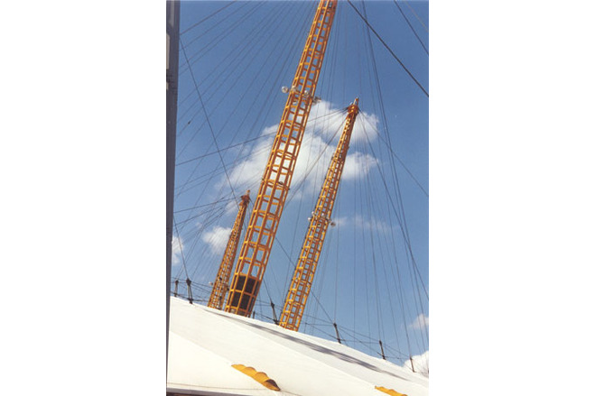
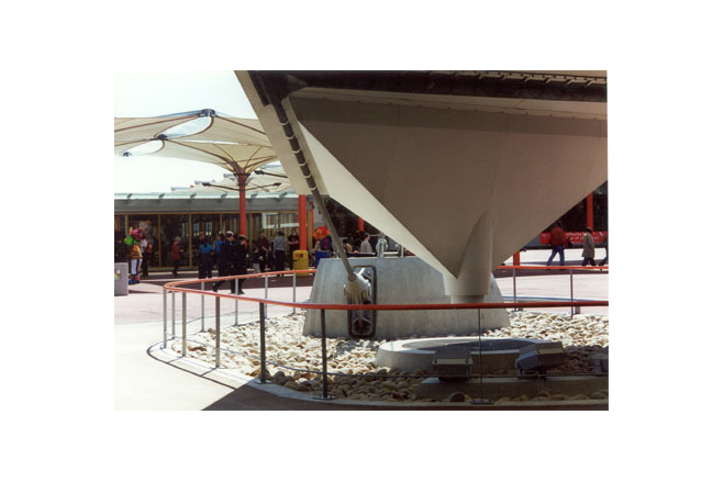
Large numbers of cable terminations greatly increase the cost of making them up, but this pays off on site, because it means that the dimensions are fixed. The radial cables were attached at intermediate points to the 90 mm boundary cables. Friction clamps were used to avoid cutting and terminating the cables. One of the most complicated 3-d problems was the detailing of the huge mastheads, where no fewer than 23 separate cables had to be connected at a common intersection point. In the course of detailing, it proved necessary to extend many of the connector plates outwards to allow the individual cable ends to connect without clashing with each other. The masts themselves were relatively simple to detail with all the joints, including the site joints, since they are fully welded. All 12 masts are identical. At the bottom of each mast is a rubber pot bearing with a single locating bolt. The bearing allows slight rotation of the mast at the connection point with the pyramid.
Design verification
The calculations to verify the safety of the design were based on our "Tensyl" program. Analysis of the cable structure has shown that the behaviour of the structure is very sensitive to cable stiffness. Each cable has been dimensioned , but also for axial stiffness, in order to ensure that the cable system does not "go soft" when under load. Wind loads were taken initially from published data and then confirmed by wind-tunnel tests. Snow loads were derived from an analysis of snowfall data and observation of the extent of drifting in various situations.
Steelwork construction stage
The steel contractor, Watson steel, had to develop the engineers' design rawings into shop drawings for the production of the components. This process involved an element of detailed design of the components and connections. The cable work was subcontracted to Bridon Ropes of Doncaster. The cables have to be wound from wires that have been previously drawn and galvanized. For the dome project, class A galvanizing - the lightest - was specified for the cables beneath the roof; and Galfan, a more durable mixture of aluminium and zinc, for galvanizing the external cables. The cables had to be prestretched to eliminate the construction stretch, and then marked to the correct lengths under the specified load. Most of the cables were dead length without any provision for adjustment.
When the net was completely assembled and all the cable lengths had been checked, each of the 72 pairs of radial cables had to be tensioned. This was undertaken in a number of steps, using a 55-tonne-capacity "Enerpac" pull jack in the predesigned jacking points at the front of the perimeter masts. Because of the flexibility of the central ring and the boundary cables, the tensioning of the radial cables had to be executed to specified dimensions rather than to specified loads, with final adjustments made at the end.
General comments, links
Fabric work
The best tender for the PTFE/glass material was submitted by Birdair from Buffalo, New York state. They have been producing structures in PTFE for more than 20 years, and their projects include 12 covered stadiums of approximately half the area of the dome. The cladding was specified in two layers to provide a degree of insulation and to reduc the risk of condensation. The outer layer is in Sheerfill 2, a medium-weight PTFE/glass fabric. The lining is in Fabrasorb, a lightweight glassfibre fabric with an open mesh weave and a minimal coating of PTFE. Buro Happold did not want to use this product, since it has a history of becoming very dirty. Unfortunately, a suitable alternative was not available , and the lining has indeed become very dirty.
The fabric attachement detail proposed by Buro Happold was a double luff groove extrusion fitted on to the radial cable pairs to accept a roped edge on the fabric. Birdair proposed a 12 mm edge cable in the fabric which was to hook into special clamps fixed to the cables. The clamps were developed into a two-part extrusion cut into 50 mm lengths and retained by two 12 mm bolts. Fabric flaps were closed over the tops of the site joints and sealed, using a hot iron at 380°C and an FEP interlayer.
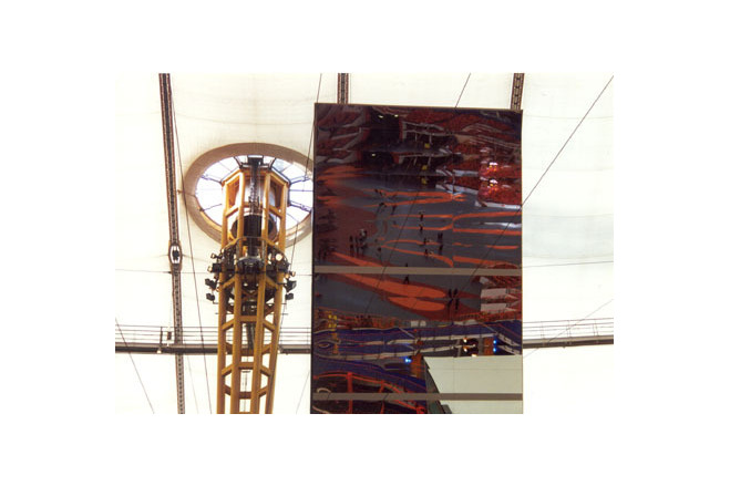
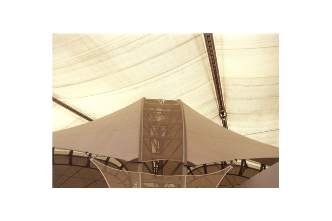
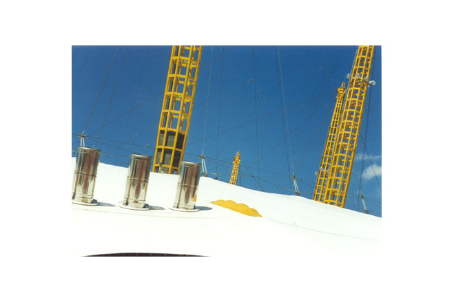
Tunnel vent enclosure
This was designed to accommodate the "air rights" of the ventilation structure. After considering various ways of leaving a hole in the fabric, Buro Happold adopted a net of 8 mm cables at 1 m spacings. This was designed to replicate the stress-carrying capacity of the fabric, while allowing the vent air to pass through. The cable net was attached to the fabric with clamp bars at the edges.
Future developments
Man has long dreamt of creating large enclosures to ameliorate the inhospitable climate in varios parts of the world. Perhaps the most famous example is a proposal by Buckminster Fuller to cover a large area of New York.
Further concepts were proposed by Frei Otto in 1970 and by Buro Happold in their "City in the Arctic" study in 1981. The built structures that have come closest to these dreams are large greenhouses, a form that has its origins in the 18th century. Currently, two very large greenhouses - each about 20000 m² in area - are being constructed for the Eden Project in Cornwall, England. They have transparent ETFE-foil cushion cladding.
The Millennium Dome cable technology could be extended to cover an area of 150000m² with ETFE cladding - in other words, an entire covered town for extreme climates.
[Detail 6/2000, Membrane Construction, p 1042, 1043]
Millennium Dome
Mobile Stages
DETAIL 1998/6
Millennium Dome in London
The Construction of the Millenium Dome, London
Material of the cover
-
Cable-net/Fabric/Hybrid/Foil
Cable
-
Material Fabric/Foil
Fiberglass
-
Material coating
PTFE
Main dimensions and form
-
Covered surface (m2)
100000
-
Total length (m)
365
-
Total width (m)
365
-
Form single element
Flat appearance
Duration of use
-
Temporary or permanent structure
Permanent
-
Convertible or mobile
Convertible
-
Design lifespan in years
06-10
Involved companies
-
Architects
Richard Rogers Partnership
-
Engineers
Buro Happold
Editor
-
Editor
Marijke M. Mollaert