Expo 1985 (Tsukuba): Suntory Pavilion


General information
-
Location address
Tsukuba
-
Location country
Japan
-
Year of construction
1985
-
Name of the client/building owner
Suntory Ltd.
-
Function of building
Exhibition
-
Degree of enclosure
Fully enclosed structure
-
Climatic zone
Temperate - cold winters and mild summers
-
Number of layers
mono-layer
Description
Design
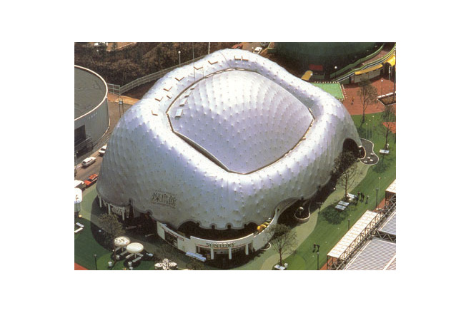
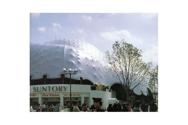
The exhibition in this pavilion stood under the mottos 'Bird Life' and 'Our future tomorrow'. The exhibition was intended to present new science and technology and to give an impression of the shape of our future society. A building in keeping with these themes was to be designed, with fluent lines and curved surfaces, resembling a gently rising hill or a bubble arising from the Earth.
Plan, use
The inside area of the pavilion was divided into three zones: an exhibition area, an auditorium with projection room and numerous ancillary rooms. The world's largest projection screen so far (26 m x 36 m) was placed in the centre of the pavilion. Around it on the first floor the various ancillary rooms were arranged. On the second floor the exhibition areas are located in the same ring-shaped plan area.
Structural concept
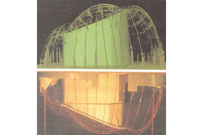
For the architect the most important design task of the first design phase was to cover the gigantic projection screen with an organically formed roof. After long consideration and investigation of different schemes a roof structure was chosen which follows a reverse catenary. In the beginning a wooden gridshell was explored, however, this would have required the solution of a number of tricky problems, like for example a decision on the required safety factors for the curved wood grid structure or satisfying the demanding fire protection requirements.
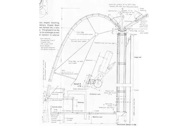
Instead it was decided to use a similar form with a structure made from planar rigid fram elements. From arch truss elements a ?naturally? curved roof shape was formed corresponding to the architectural concept. Under the circumstances this appeared to be the best solution for the construction of the desired shape and for carrying the considerable wind loads.
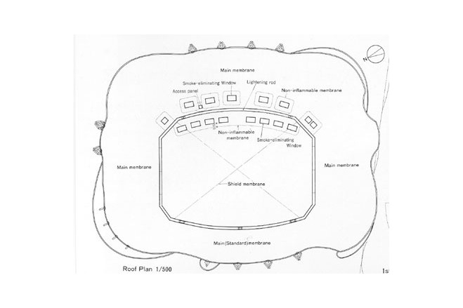
Fire protection
For fire protection smoke vents and short, vertical flameproof drop walls in the roof area had to be provided as separations for the fire compartments of the automatically opening smoke vents. In the projection room a fire shutter was required to close this area against the auditorium in case of a fire. Also for fire protection in the lower membrane area up to 4 m above the floor a roof membrane of PVC-coated glass fibre fabric had to be used.
Structure
The structure has a conventional reinforced concrete substructure, exposed concrete walls, floor slabs as well as strip and pad foundations, reaching from the foundations up to the exhibition area in the second floor. The structure above consists of three parts:
- the auditorium walls,
- the roof of the auditorium, and
- the ring-shaped roof of the exhibition areas.
Wall
The walls of the auditorium are set up as cavity walls ; they consist of two rolled steel sections connected by gusset plates,which form a Vierendeel strut. They are clad on both sides with gypsum plasterboard. A twin ring beam made from steel tubes lies in the upper wall edge.
Description of the environmental conditions
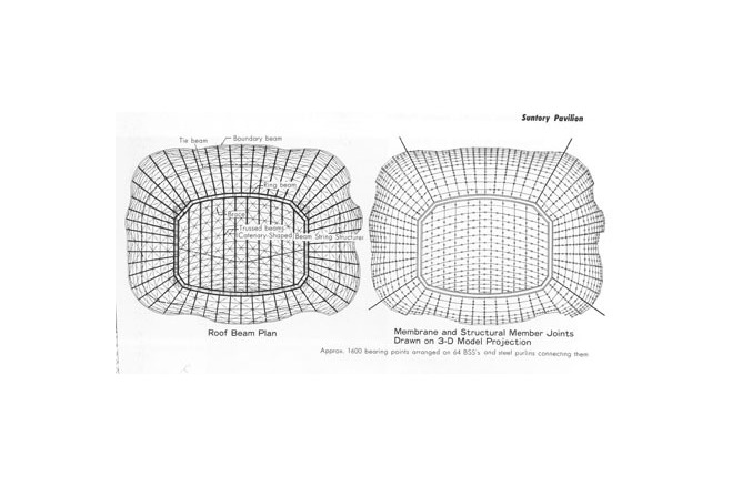
Roof
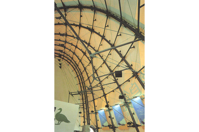
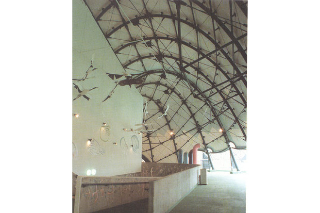
The auditorium roof consists of 10 truss arches in the shape of a catenary, which in plan are arranged parallel to each other and which are pin-supported on a ring beam. The roof of the exhibition area has the same structural system, however, with a radial arrangement of the arch trusses.
The planar arch trusses consist of steel tubes (Ø 267 x 9.3 mm in the outer roof and Ø 267 x 7.1 mm above the auditorium) with round bar tension ties (Ø 25 mm) and compression struts (CHS Ø 101 x 4.2 mm). They are pin-supported on the edge and ring girders.
The tension ties are equipped with welded end plates (t = 19 mm), which are connected via short connecting plates (t = 19 mm) and with two bolts each to the chord tube and to plates welded onto the strut head (t = 19 mm). At the tensile nodes the round bar diagonals are connected via short connection plates of similar construction (also with two bolts each) to circular steel plates (t = 19 mm).
According to the type of loading, part of the tie suspension will go slack and therefore not carry load, which was taken into account in the structural analysis as a change of the structural system.
In the area of the compression struts the arches are connected at right angles to the arch plane by steel tube compression members and braced against lateral buckling by tie cross-bracing in the plane of the arch chord.
The straight steel tube joists (O 89 x 4.2 mm) are placed in the centre plane of the arch chords and are connected with it via steel plates and machine bolts.
Edge structure
In the edge area the roof is supported by three-dimensionally curved edge beams, which shed their load into A-shaped steel trestles standing outside the building.
The A-shaped supports consist of an external steel tube compression strut with a welded steel plate tripod construction. The outer compression member is furnished on top with a conical reduction and a spherical head. There connection strips are welded on to receive the edge beams.
The edge beams consist of two steel tubes connected with truss diagonals. They are bolted to the A-trestles, on the outside with steel plate strips and on the inside using a pipe flange. They carry the arched roof beams, which are connected via a pin connection and welded steel strips to the plate stiffeners.
Along the reinforced concrete edge the arches are pin-connected on steel supports. These supports are fixed onto the horizontal concrete surfaces by means of anchor bolts and a mortar bed.
General comments, links
Membrane
The roof membrane is supported on approx. 1600 high points on the arches and joists. The position of these support points was determined by computer during the form- finding stage, while simultaneously controlling the surface shape to achieve the desired roof form.
The material is PVC-coated polyester fabric treated against surface spread of flame, with a tensile strength of 400 kg/5 cm (warp) and 365 kg/5 cm (weft/fill).
In the lower membrane area, up to 4 m above the floor, it was replaced for reasons of fire protection by a PVC-coated glass fibre fabric and at the interface welded to the PVC-coated polyes- ter membrane. The areas around the smoke vents are also made of this PVC-coated glass fibre (for the same reasons).
At the high points the membrane is supported and fixed in position by two circular steel plates (Ø 220 mm) with a central machine bolt and reinforced by a membrane patch on the outside and inside. The lower circular plate is welded onto a steel tube spreader, which is welded to arches and joists in a direction perpendicular to the roof surface. Some of the high point props are adjustable in angle and length, so that the membrane can be prestressed and tolerances can be equalised. For this a threaded bar with ball head is located in a welded bearing held at the prop end and screwed into a threaded sleeve. At the other end of the sleeve a machine bolt is screwed in, clamping both circular plates against the membrane.
Along the tubular beams the roof membrane is connected by lacing to a tube (Ø 25 mm) running parallel to the tube beam and connected at the edge beams by short welded plate strips. In front of the lacing a decorative cover strip is fixed, which hides it from view. This strip is bent and cut into a ring shape around the ball heads on top of the A-trestles, emphasising the support. At the entrances a gutter is provided under the lacing, shedding the rainwater to the side.
At the concrete edges the membrane is also fixed via a covered lacing to an uninterrupted tube section (Ø 25 mm), which is fastened to the reinforced concrete by short plate strips. In the upper roof area the membrane edges are detailed in a similar way ; here a membrane apron covers the lacing connection to the Ø 25 mm tube and at the same time sheds the rainwater into a box gutter, lying between the two ring beams on top of the wall.
In the ring-shaped outer roof area the membrane is subdivided by four site joints. The four roof panels are again connected through lacing to a steel tube (Ø 25 mm). The joint is covered and sealed from the outside by a membrane strip.
[Soft Shells, Hans-Joachim Schock, p106, 109-110]
Membrane Design in Japan (1967-1990)
Suntory Pavilion, Expo'85, Tsukuba, Japan
Material of the cover
-
Cable-net/Fabric/Hybrid/Foil
Cable
-
Material Fabric/Foil
Polyester
-
Material coating
PVC
Main dimensions and form
-
Covered surface (m2)
2420
Duration of use
-
Temporary or permanent structure
Temporary
-
Convertible or mobile
Convertible
-
Design lifespan in years
00-05
Involved companies
-
Architects
Institute of International Environment
Keizo Sataka
-
Engineers
Masao Saitoh
T.I.S. & Partners
-
Contractors
Editor
-
Editor
Marijke M. Mollaert