Garage Park Montreux


General information
-
Home page
www.canobbio.com
-
Location address
Montreux
-
Location country
Switzerland
-
Year of construction
2004
-
Function of building
Vehicle services
-
Degree of enclosure
Open structure
-
Climatic zone
Temperate - cold winters and mild summers
Description
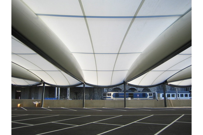
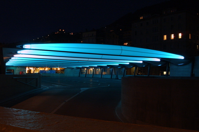
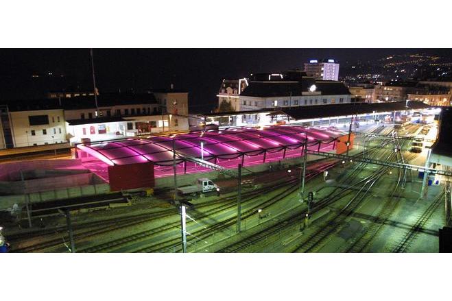
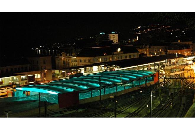
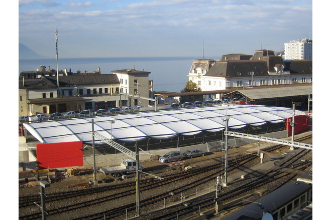
The roof of the last floor of the Garage Park of the Montreux railway station (Switzerland) designed by architect Luscher in co-operation with engineers Pedretti (Airlight Ltd., Biasca, Switzerland) covers an area of 1700 m2 and is composed of 12 Tensairity® beams of about 27m span, and 11 sections of tensioned single saddle shaped membranes supported by the Tensairity® beams and the vertical steel supporting structure.
The general Contractor was Zschokke Enterprise Generale (Switzerland), which has subcontracted the steelworks to Z&M (Aigle, Switzerland) and the manufacturing of the beams and the membranes to Canobbio SpA (Italy).
During the design phase it was pointed out that a special silicon coated fiberglas fabric was the most suitable fabric; this due to the excellent fire proof behaviour, the fact that it does not develop toxic gases, has good resistance and stabilizing properties and a high light transmittance.
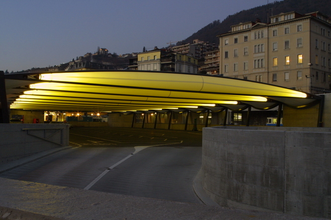
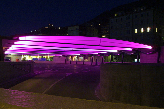
As for the Breitling project, the architect has used the beams as light elements for the whole surface. This is a very nice and interesting system as it is possible to obtain different light effects.
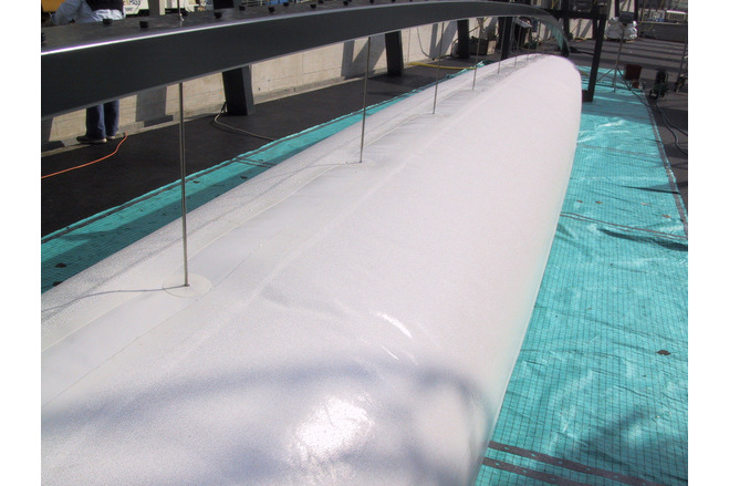
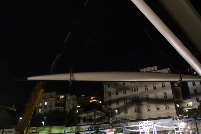
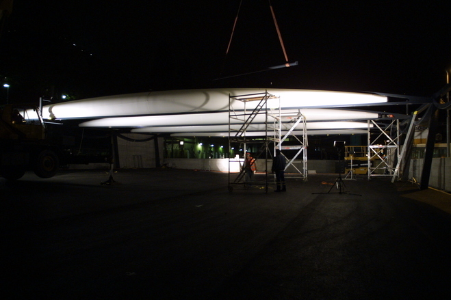
About erection and installation: the air beams have been previously assembled in the Z&M workshop and then transported once they were complete and stable. The transport was done by train in order to reach the site in the easiest way. Access to the site was in fact not possible with another kind of transport.
Once there, the beams have been lifted with cranes and positioned on the vertical supporting structure. All this has been done during the nighttime in order to avoid any interference with the daily railway traffic.
Afterwards the saddle shaped panels have been installed and fixed to the beams by means of an aluminium ?keder? profile and tensioned at the perimeter.
Laboratorium Blum (Stuttgart) has spent a large period of time to be able to characterise the fabric behaviour. Several biaxial tests were fulfilled to be able to optimise the calculation and to find the adequate compensation factors to apply.
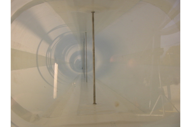
A few problems have also been solved to obtain the best air tightness of the beams; those beams are provided with a control system and an air inflating equipment which checks and keep the pressure inside the beams always at admissible levels. The fabric has been modified a few times in order to minimise the silicon porosity, the loss of air by the seams and above all the loss of air in the intersection between the threaded rods and the upper and lower steel element.
The static calculation of the covering has been executed with the finite elements program ANSYS 7.1, in particular for what concerns the Tensairity® beams and the saddle shape membranes that link them. This type of structure requires advanced computer calculations because of its double non-linearity: geometric on one hand ? important displacements ? and for the behaviour of the materials on the other hand.
The calculation of the Tensairity® beams must take place by stages. The first consists in applying the load given by the interior pressure of the air tube only. The resulting efforts and the displacements are then used like initial conditions for the second stage where the external loads are added to the structure in different steps.
Description of the environmental conditions
Material of the cover
-
Cable-net/Fabric/Hybrid/Foil
Fabric
-
Material Fabric/Foil
Fiberglass
-
Material coating
silicon
Main dimensions and form
-
Covered surface (m2)
1700
-
Total width (m)
27
-
Form single element
Anticlastic
-
Form entire structure
Flat appearance
Duration of use
-
Temporary or permanent structure
Permanent
Involved companies
-
Architects
Luscher
-
Engineers
Pedretti (Airlight Ltd.)
-
Contractors
Canobbio spa
Zschokke Enterprise Generale
Z&M
-
Suppliers
P-D Interglas Technologies Ltd.