Sea & Island Expo 1989 (Hiroshima): Exhibition Building 'Big Wave'


General information
-
Location address
Hiroshima-city
-
Location country
Japan
-
Year of construction
1988
-
Name of the client/building owner
Sea & Islands Expo Association
-
Function of building
Exhibition
-
Degree of enclosure
Fully enclosed structure
-
Climatic zone
Temperate - cold winters and mild summers
Description
Design
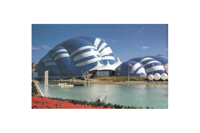
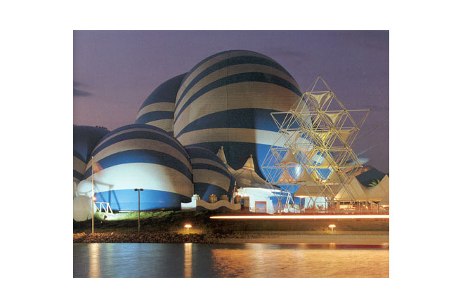
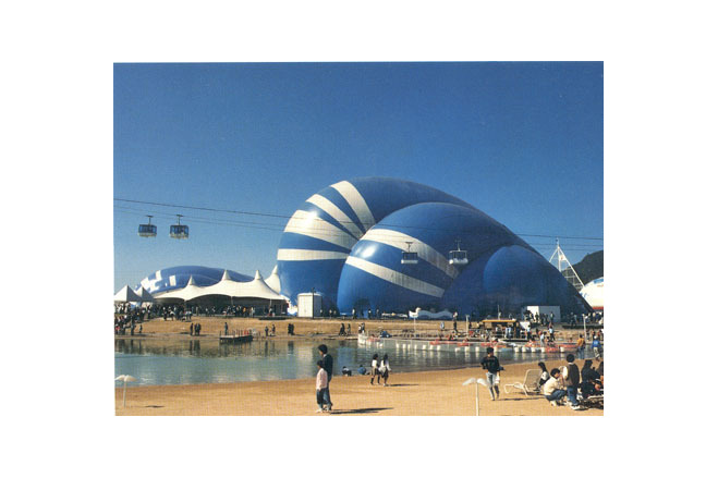
The concept of this unorthodox and spectacular exhibition building for the Sea & Island Expo'89 in Hiroshima sprang from the wish to graphically express Hiroshima's particular geographical and climatic situation by the sea: as an easy, playful expression of a message for world peace in yhis city destroyed by the atomic bomb. Nowhere else is there such a large building, which has the three-dimensional shape of waves. For this purpose the 'Ukiyoe' pictures by the Japanese painter and graphic artisi Hokusai were studied and transferred into a built form: the whole range of wave movements and wave forms, restless intermediate areas, the breaking of the waves at the shore and the froth they leave behind.
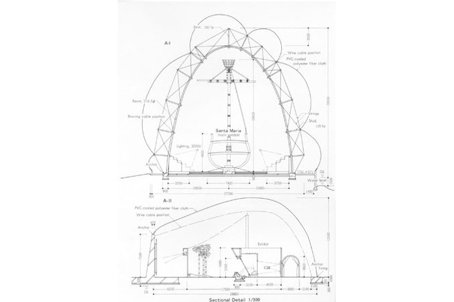
Two large exhibition areas were to be created: one for a 20-m high, full-scale section model of the flagship of Christopher Columbus, the 'Santa Maria', and one for a large show object smaller in height and including an audio-visual display.
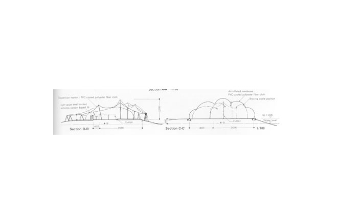
For the representation of the wave form for both areas a pneumatic, air-supported structure was chosen. Hall 1, with a required room height of max. 30 m, was braced by a substructure of curved, cable-braced steel trusses, to avoid the large displacements under wind load common for a steep pneumatic structure. A flat connecting area between the two "waves" is designed as an open, mechanically prestressed tent structure in the form of a high point membrane with inner masts.
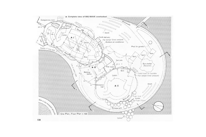
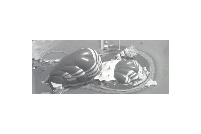
Plan
The exhibition hall lies on a peninsula amid an artificial stretch of water with a beach. Nearby passes a funicular cable car. In the long, narrow Hall 1 with elliptical plan the display object Santa Maria and some associated exhibits are located, with seating tiers for the visitors, various storerooms and entrance and exit areas with the necessary airlocks for people and goods as well as access ramps. As a connection between Halls 1 and 2 a lounge area with catering was inserted as a buffer zone, which also contains the plant room for blowers and standby generators. The plan form of Hall 2 is irregular, it resembles a circle with small bulges and results from the outer wave form and from the compact form of the audio-visual display shown there.
Structure
In the area of Exhibition Halls 1 and 2 the structural system is an air hall, I.e. a roof membrane of coated fabric supported and stabilised by inside air pressure. In the connecting area the structure is a mechanically prestressed high-point membrane, which is reinforced on the outside by edge cables and held in position by edge masts and guys. All along the reinforced concrete walls facing the air-supported parts the membrane is fastened to the walls and drained through a gutter there.
Membrane
The roof membrane of the air halls is composed of opaque PVC-coated polyester fabric, likewise the mechanically tensioned, anticlastic (saddle-shaped) membrane of the connecting part. The structural seams are carried out as a combination seams, I.e. welded and sewn seams combined and was partly sealed with external weather-strip, welded over with hot air.
Description of the environmental conditions
Air halls
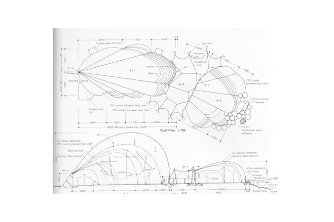
The shapes of the air-supported waves can be interpreted approximately as torus or translation surfaces, with the valley cables as directrix.
The air-supported structure is stabilised through inside air-pressure, which at standaard conditions amounts 20 mm water gauge and can be increased if required up to 40 mm water gauge, to provide the necessary stiffness for extreme wind speeds. (The design wind speed because of possible typhoons is 60 m/sec = 216 km/h).
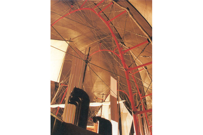
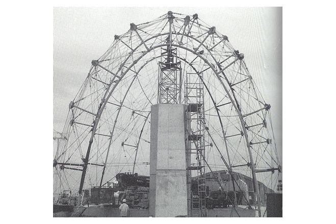
The individual membrane parts are strenghtened through valley cables. Their anchorages in Hall 1 are located in a wall shaped, 7,5 m high reinforced concrete support on the entrance side near the airlocks, on the other side the valley cables are connected at a 4,5 m high reinforced concrete wall. In hall 2 the valley cables proceed from a 7,5 m high reinforced concrete wall on the one side to anchorages at a low level in the strip foundation on the other side. In Hall 1 the garland-shaped valley cables are connected to a substructure of prestressed, cable-braced compression arches. These form a planar, bending-stiff truss as a lateral bracing. The individual trusses have a steel tube bottom chord with bolted flange connections and reinforcement ribs, a top chord from prestressed steel cables, steel tube web members and cable diagonals with turnbuckles. In transverse direction the truss elements are braced laterally with prestressed cable ties, which proceed from the compression chord of one truss to the tension chord of the other.
In the valleys the membrane is joined with a structural valley apron membrane, lying above the valley cable, through sewn and welded membrane reinforcement strips. This valley apron is reinforced at the edge with a thin edge cable (boltrope) and is connected intermittently with steel plate strips, machine bolts and metal eyelets to the valley cable.
At the edge of the air halls the roof membrane is finished with garland-shaped edge cables, running in membrane pockets. The continuous edge cable is anchored point by point through shackles and connecting plates with U-bars cast into the reinforced concrete foundation. The roof membrane continues as a membrane apron across the edge cable and lies loosely on the concrete foundation, where it is pressed on by the inside air pressure. To transfer the tangential forces from the edge cable pockets these are fastened to the corner plates with thin plate strips. The corner plates transfer their loads by means of rounded anchor shackles and cast-in round steel U-bars in the foundations.
Connecting area
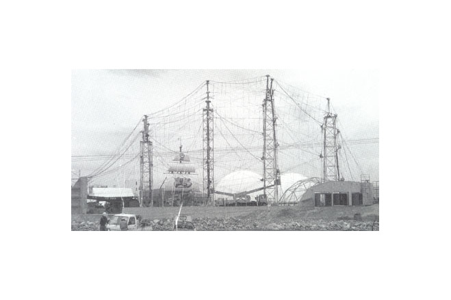
The transition between the two wave-shaped air halls is formed by a high point membrane with six inner high points, edge cables and edge masts with guys on two sides. At the remainig sides the roof membrane is fixed onto the reinforced concrete structure of the 'waves'.
The high points are carried by steel tube masts, where the membrane is connected via high point rings. The masts proceed through the high point above where they are joined with each other through a system of security cables. These serve to secure the masts or other structural elements against collapse in case the membrane was destroyed through an extreme loading condition. The high point rings are closed by conical covers.
[Soft Shells, Hans-Joachim Schock, p119, 121]
General comments, links
Big Wave Sea & Island Expo'89
Exhibition Building 'Big Wave', Hiroshima, Japan
Material of the cover
-
Cable-net/Fabric/Hybrid/Foil
Cable
-
Material Fabric/Foil
Polyester
-
Material coating
PVC
Main dimensions and form
-
Covered surface (m2)
2781
-
Total length (m)
27.2
Duration of use
-
Temporary or permanent structure
Temporary
-
Convertible or mobile
Convertible
-
Design lifespan in years
00-05
Involved companies
-
Architects
Institute of International Environment
Keizo Sataka
-
Engineers
Institute of International Environment
Gengo Matsui
-
Contractors
Taiyo Kogyo Corporation
-
Suppliers
Taiyo Kogyo Corporation
Editor
-
Editor
Marijke M. Mollaert