Trade Fair stand for the 'Automechanica' in Frankfort (Germany)


General information
-
Location address
Frankfurt
-
Location country
Germany
-
Year of construction
1994
-
Name of the client/building owner
Kleindienst Waschanlagen, Augsburg
-
Function of building
Exhibition
-
Degree of enclosure
Fully enclosed structure
-
Climatic zone
Temperate - cold winters and mild summers
Description
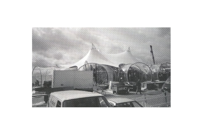
Together with the trade fair architects of the office WNS Design in Wiesbaden the project A Filling Station of Tomorrow (30 x 20 m in plan) was to be developed on behalf of a carwash plant manufacturer. A futuristic design and details using new materials, new ideas - innovative, visual and functional - was requested for the archetypal concept of a filling station.
The stand was to be demountable and should contain a novel filling station with space for several cars. The first station of this type was erected in the open-air at the IAA-Fair in Frankfurt, with the possibility of further uses by the client for information and promotions.
Design
The architects and the membrane technology experts from IF worked together on novel building materials, particularly concentrating on fabric-reinforced plastics and foils and on develop- ing the membrane detailing. The detail development owes much to ship building, and in this case especially to the design of the large sailing yachts on Lake Constance. The fittings and fixings, cables and masts of these yachts are part of a technology which has developed over centuries and become standard in daily construction tasks. In this field examples and models for the solution of many detailing problems like cable anchorings and prestressing and adjustment solutions could be found, and these ideas were then modified for the kind of specific, one-off production which is still a necessity in the construction industry.
Structure
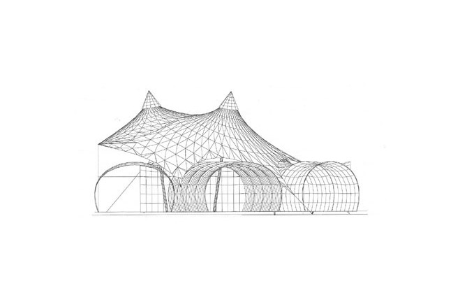
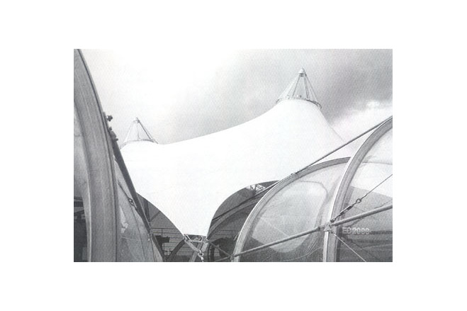
The roof membrane in the main structure is self-supporting. In the interior of the main roof there are three steel tube masts with high point rings and with a conical, clear transparent cover ; these masts carry the roof.
Along one side the roof has a straight edge. There, short steel tube sections (O 26.9 mm) are placed into a membrane sleeve, cut out intermittently with semi-circular cut-outs, and anchored at keys welded on along the bending stiff edge made from a steel I-section lying on its side.
The service cabins inserted under the edge cable arches of the main roof membrane consist of tubular aluminium three-centre arches fixed at their base with a transparent foil stretched over it.
Foundations
Due to its construction on the trade fair, special foundations like tension foundations or gravity anchors with large concrete volumes in the ground were not possible. Therefore a steel grid was chosen to spread the loads, the weight and stiffness of which is sufficient, together with the weight of the simple pad foundations and of some external tension ties, to prevent uplift of the structure under wind.
Description of the environmental conditions
Membrane
The main membrane consists of PVC-coated polyester fabric, type I, and the foil cover of the arches of clear transparent ET-foil (Hostaflon).
Along the edge the membrane is reinforced and held by an edge cable. It runs in membrane pockets. An additional edge webbing transfers the tangential membrane forces and allows an independent adjustment to be able to equalise production tolerances. The edge cables are equipped at the end with steel thimbles and swaged aluminium sleeves and connected with a standard shackle to the corner plate. The edge webbing is sewn up at the end with the triangle ring and joined to the corner plate via an adjustable connection.
To this end a threaded rod is bent into a triangular ring and welded up ; the threaded bar runs through a tube sleeve welded into the triangular plate, where it is anchored with a tensioning nut. The corner plate is connected with the edge mast and its guy structure via an adjustable eye bar, consisting of an eye plate with a slotted hole to receive the associated shackle and of a threaded bar which is welded on. Here, too,the threaded bar runs in a tube sleeve welded into the corner plate and anchored with an tensioning nut. At a direct guy without edge-mast the eye bar is replaced by a standard shackle passing through a hole in the corner plate, to which the guy cable is attached via a steel thimble.
Foil roof
The foil cover has an edge boltrope welded in, which is inserted into a curved aluminium boltrope extrusion, similar to that used in large frame tents. The arch structure is braced in a longitudinal direction by stainless steel cable crosses with thimbles and fork turnbuckles and with steel tube struts, fastened to anchor plates bolted to the arches.
[Soft Shells, Hans-Joachim Schock, p111, 113]
Material of the cover
-
Cable-net/Fabric/Hybrid/Foil
Foil
-
Material Fabric/Foil
Polyester
-
Material coating
PVC
Main dimensions and form
-
Total length (m)
30
-
Total width (m)
20
Duration of use
-
Temporary or permanent structure
Permanent
-
Convertible or mobile
Convertible and mobile
-
Design lifespan in years
00-05
Involved companies
-
Architects
IF Ingenieurgemeinschaft Flächentragwerke
-
Engineers
IF Ingenieurgemeinschaft Flächentragwerke
-
Contractors
Strohmeyer & Wagner GmbH
Editor
-
Editor
Marijke M. Mollaert